This thread has been locked.

If you have a related question, please click the "Ask a related question" button in the top right corner. The newly created question will be automatically linked to this question.

LM393: pull up resistor

Expert 1045 points
Part Number: LM393

Excuse me,

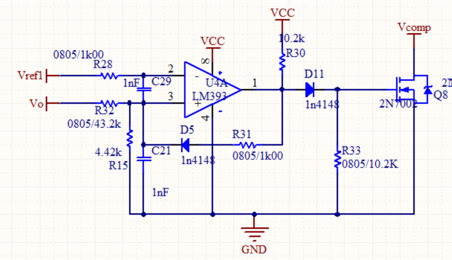
I am using LM393 to do the OVP circuit and I found a  OVP circuit in google and I have some questions

1.) How to calculate the pull up resistor, the pull up resistor is based on the LM393 output sink current?  if the output sink current is 10mA and the VCC is 12V so the pull up resistor is 12/10mA?

2.)in this circuit, is this a hysteresis schmitt circuit?

3.) The C21 is a filter capacitor, but the C29 is also the filter capacitor? If this is also filter capacitor why it connect Pin2 to Pin3, not Pin2 to Ground?

4.) why this circuit need use D5 and how it work?

hope someone can help me understand this circuit

  • Hello,

    1. The resistor is selected to provide the desired amount of current when the output is "low".

    Please see section 3 to 3.2  of the LM393 family appnote:

    Application Design Guidelines for LM339, LM393, TL331 Family Comparators (Rev. A)

    We recommend a pull-down current around 1mA. 10mA is getting close to the short circuit current limit. So 10k is good (12V/10k=1.2mA).

    2.  They are attempting to add hysteresis, but it is being negated by C21. The presence of a capacitor from the positive node to another node will negate the effect of hysteresis, as the cap adds a delay to the feedback.

    3. In this case, it looks like they intended C21 to act as a filter - but it also delays the hysteresis. C29 also causes a delay. Normally we do not recommend adding a capacitor between the inputs as it can add additional propagation delay and cross-talk onto the reference line.

    As this is an overvoltage circuit, I assume we are not looking at fast (<10ms) input signals, so the caps will probably not hurt. But if you see short "bursts" of output signal right as the threshold is crossed, then this is caused by the capacitors.

    4. Diodes are commonly used to add "asymmetrical" hysteresis. In this case, hysteresis will only be applied to the rising edge of the output.

  • Thanks for your reply, and I still have some confused

    1.)I know the cap will cause the delay in the circuit, but how do the cap will affect the  hysteresis?

    2.) you said the cap C21 negate the effect of hysteresis, because the cap adds a delay to feedback?

    a. If we want to have a effect of hysteresis, I need to remove the cap, it mean I can't add any cap in the input port right?
    b. If I cannot add any cap in the input port, how do I filter the noise?

    3.)  I know the hysteresis but I don't have any ideal about asymmetrical hysteresis, what's the asymmetrical hysteresis, can you give a example about this and figure let me can quickly understand.

    4.)As this is an over voltage circuit, I assume we are not looking at fast (<10ms) input signals, so the caps will probably not hurt. But if you see short "bursts" of output signal right as the threshold is crossed, then this is caused by the capacitors. what is that mean


  • Hello,

    1.) Hysteresis (positive feedback) works by quickly shifting the input slightly positive on the very first transition of the output, to prevent further transitions ("chatter" or "noise"). If a capacitor is placed on the positive node, then the capacitor must charge-up before the reference shifts (adds a time constant), so that "shift" is delayed and a few chatter transitions may get through.

    Please see the Hysteresis appnotes for more information:

     Inverting comparator with hysteresis circuit (Rev. A)

     Non-inverting comparator with hysteresis circuit (Rev. A)

     Comparator with and without hysteresis circuit (Rev. A)

    2.) Yes. See the above..

    2a.) Yes. There must be a series resistance on the input  for the hysteresis feedback to "work against", to allow the shift. The hysteresis is the ratio of the feedback resistor to the source resistance.

    2b). You can have a "filter" capacitor, but then you must add the second hysteresis resistor after to allow the "slip" needed for the hysteresis.

    3.) Sometimes it is desired to have a larger shift in the hysteresis in the positive or negative direction, such as a 10mV shift on the rising, and a 20mV shift on the falling. This can be done by using two different feedback resistors that are selected by diodes, just like is done with D5 and R31 (but there would be a second parallel resistor, with a diode pointing the opposite way). The output state sets which feedback resistor is used.

    4.) As mentioned above, if the feedback is delayed, it may miss a few cycles of "chatter" as the input crosses the threshold.

  • I have three part I don't understand

    1.)In your reply 3.)(asymmetrical hysteresis) I know what you said , but do you have some data talk about this? because I still confused, the waveform how it look like

    2.) I see the datasheet you give me, in the datasheet it tells us, where the output voltage sharply inflects upwards in the 10-20mA region. This region must be avoided as the specified minimum short circuit current is only 6mA (typically 12-16mA) and can vary across devices, lots and temperature

    a.) This graph is LM393 output VoL and IoL, why can not operate in the 10-12mA,(datasheet  said the IoL range is between 6~21mA) it will damage to the LM393?

    3.) what is the chatter

    1. I would recommend searching the Web for more information on asymmetrical hysteresis as I am still looking for TI documentation on this issue.
      1. Simply put, the diodes allow current to flow 1 way. This means that with two diodes and two feedback paths in parallel (with different feedback resistors like R31), that each threshold will have a different amount of hysteresis.
    2. The low level output current has a typical value of 6 mA that can increase with temperature. As far as the rest of this question, I don't know what section of the datasheet you are looking at and what do you mean by output voltage inflecting upwards in the 10-20mA region?
    3. By chatter, Paul is referring to the output of the comparator oscillating when the input is has noise around the threshold value. Hysteresis is implemented to avoid this from happening.

    Regards,

    Joe

  • 1.) OK, I will research this 

    2.) I watch this Ti document Application Design Guidelines for LM339, LM393, TL331 Family Comparators (Rev. A)

    3.) I got it

  • For your second question, what specific tables and figures are you referencing in the datasheet? This will help me better answer your question : )

    Thanks,

    Joe

  • in the 3.Output Stage Considerations

  • This section highlights the recommended sink current. For this open-collector part, if you use a pull-up voltage of 5V then using a 10kOhm resistor would result in a sink current of 2.5mA. This is within the recommended range of sink currents (<5mA). Does this answer your question?

    Regards,

    Joe

  • No, I want to ask about figure 8.
    in the figure 8 the datasheet said This region must be avoided as the specified minimum short circuit current is only 6mA (typically 12-16mA) what's that mean

  • TI recommends sinking currents of less than 5mA through the output of the LM393. The plot illustrates that with increase in temperature, the output low (logic low) value will also increase.

    This section discusses the importance of pull-up resistor selection.

    First, look at the curve corresponding to the temperature you are operating the device at.

    Then, select a resistance that puts your output sink current in the recommended range (<5mA). 

    I recommend looking at the example in this section.

    Regards,

    Joe

  • I know this figure, but I don;t know why I can't put sink current >10mA, just because the power loss?

  • I encourage you to look at section 8.1: Application Information

    Regards,

    Joe

  • I got it