This thread has been locked.

If you have a related question, please click the "Ask a related question" button in the top right corner. The newly created question will be automatically linked to this question.

INA125: Amplitude of output signal

Part Number: INA125

V+in and V-in meaning

 I am interested about Load Cell Millivolt (mV) Output Calculator for my application, and my product enquiry is...
V+in and V-in meaning
I am using load cell (strain gauge and I want to calculate the Vout . The formula given is Vout = G·(V+in – V-in) + Vref , but I can’t find the V+in and V-in in the product datasheet?

V+in and V-in represent the voltage applied to each side of load cell strain gauge bridge circuit of the force sensor. This is typically V+in = +10 volts and V-in = 0 volts, but it could be other positive and/or negative voltage values. The difference between the two values is what powers the sensor and controls the amplitude of the output signal.

If load cell (+sig and -sig ) connect with INA125UA/2K5 pin(+Vin and -Vin) then what is exact output on +Vin and -Vin(amplitude of output).In which range value should be swing?


Please tell me as soon as possible

Thanks and Regards
Siddhi Naik

  • Hi Siddhi,

    Q: I am using load cell (strain gauge and I want to calculate the Vout . The formula given is Vout = G·(V+in – V-in) + Vref , but I can’t find the V+in and V-in in the product datasheet?

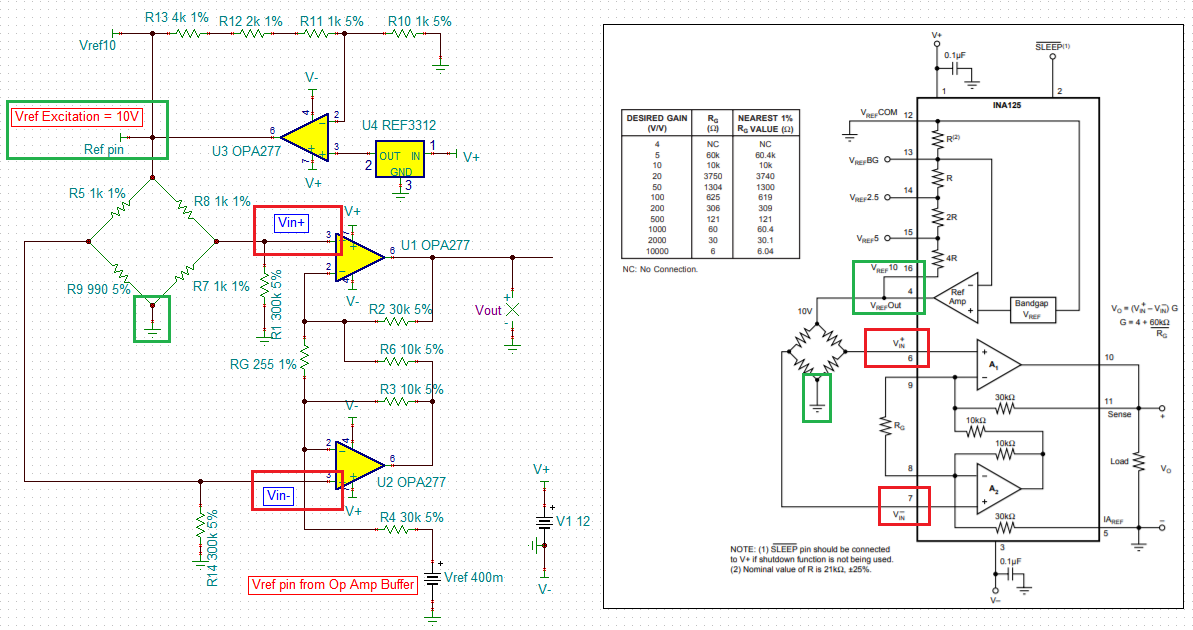
    You stated "V+in and V-in represent the voltage applied to each side of load cell strain gauge bridge circuit of the force sensor.". The strain gauge signal is very small, typically in uV to mV range. The excitation voltage to the wheatstone bridge, say 10Vdc from pin4 of Vref_out, the V-in = 10/2 - stain_gauge signal change = 5V - stain_gauge signal change, V+in = 10/2 = 5V,  Therefore, Vout = G·(V+in – V-in) + Vref, where (V+in – V-in) = 5V - (5V - stain_gauge signal change) = +stain_gauge signal change. +stain_gauge delta signal will be amplified by the INA125 + Vref (pin5) via Vout = G·(V+in – V-in) + Vref .

    V+in is not +10 volts and V-in  is not 0 volts. You may have an integrated strain gauge module (4 wires), where it requires to feed in 10Vdc reference and connect other supply lead to ground, but there should be total 4 wires. Other two wires (+sig and -sig ) should be connected to V+in and V-in, input of INA125. 

    For dual supply rails configuration in INA125, if V+in > V-in, then the G·(V+in – V-in) will be positive, V+in < V-in, the G·(V+in – V-in) will be negative.

    If single supply rail configuration is used in INA125, V+in > V-in is required. You can measure the output polarity of the strain gauge, when load is applied to a transducer. You will need high resolution DMM to measure the dc voltage, since the delta voltage will be very small in uV or mV (depending on the strain gauge). 

    /cfs-file/__key/communityserver-discussions-components-files/14/5582.INA125-Bridge_5F00_Amp-Strain-Gauge-01122021.TSC

    Q: If load cell (+sig and -sig ) connect with INA125UA/2K5 pin(+Vin and -Vin) then what is exact output on +Vin and -Vin(amplitude of output).In which range value should be swing?

    Vout = G·(V+in – V-in) + Vref is the transfer function to determine the output voltage swing. 

    Gain = 4 + 60kOhm/Rg, In the simulation example above, Rg=255 and Gain = 4 + 60kOhm/255 = 239.294. I am enclosing the pseudo simulation so that you can play around the model on your own. This is a signal supply model, and Vref needs to be above 0.3V (I set Vref at 0.4V in the example for a single supply rail). 

    If you are using dual symmetrical power supply to power INA125, Vref may be configured at 0V or connect it to ground. 

    If you have other questions, please let us know. 

    Best,

    Raymond