A related question is a question created from another question. When the related question is created, it will be automatically linked to the original question.
If you have a related question, please click the "Ask a related question" button in the top right corner. The newly created question will be automatically linked to this question.
I'm with Kai. I'm still confused. Are you looking at the TINA SPICE model, the schematic from the INA199 EVM? The images posted did not come through either.
Second, you ask about using a fixed load, are you talking about using a load to set a DC current through the shunt resistor? I need some detail into what your asking here to be able to help.
The customer has a non-isolated 100nF cap on the output of the INA199. This is 100x the maximum capacitance allowable by the device:
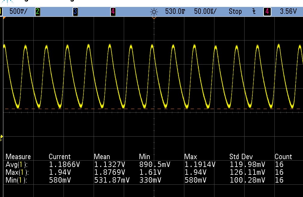
This is most likely the cause of the oscillations. I would advise the customer either remove this capacitor, or reduce the magnitude to less than 1nF, and they should see improvement in the measurement.
Ian, would it be possible to get scope shots of the output as well as the corresponding input that is leading to this? If the customer can, I'd like them to probe directly at the IN+ and IN- pins, not at the shunt.
Also, can the customer share if there is anything else connected downstream on the output? What else does 'CSM' interface with on the board?