This thread has been locked.

If you have a related question, please click the "Ask a related question" button in the top right corner. The newly created question will be automatically linked to this question.

THS4631: input bias current

Part Number: THS4631
Other Parts Discussed in Thread: THS4531

Hello Support team,

I want to know more detail regarding below post.

Could you let me know about more detail structure what ESD diodes used to protect the input from differential over voltage are not symmetrical. If you can show the block diagram, it is very helpful for my understanding it.

What does "net current" mean?

Best Regards,
Hirokazu Takahashi

  • Hello Hirokazu Takahashi, 

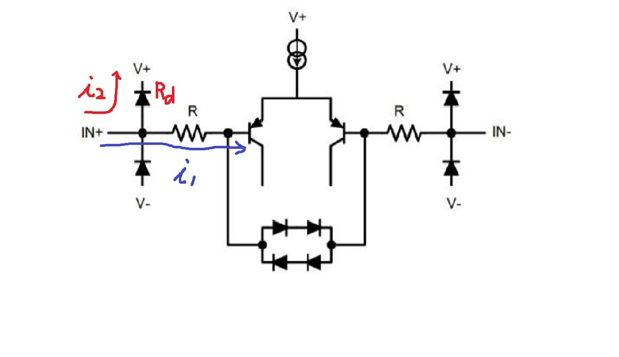
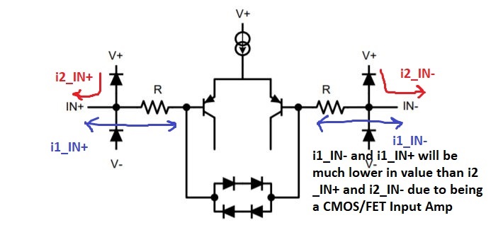
        Here is a common ESD structure (note: this is not specifically for THS4631):


    From the thread you have linked, it seems like there are also ESD diodes between the inputs of the amplifier to protect the device from excess differential voltage. Randy is talking about a net current that is produced from these internal ESD diodes at high input voltages. This net current he is referring to is the difference in bias currents or the input offset current which is mainly produced by the leakage current of the diodes. Apparently, this device was built with non-matching input structures (inverting vs non-inverting input), which is causing a relatively large non-cancelling bias currents (in this case, the bias current from the non-inverting input is much larger than the inverting input). This creates an additional offset voltage of the amplifier due to bias current * resistance. I will confirm this thought with the design engineer, and get back to you early next week. Here is a video that also goes over that concept, time segment: 10:40 to 11:10. 

    Thank you,

    Sima 

  • Hello Hirokazu Takahashi

       I received word from the design engineer that the asymmetry is with the ESD diode's capacitance. He said: when there is a high impedance on the input, the current will slowly cause the voltage in the input to change thus producing a time varying Vos. The leakage is frequency dependent; that is, the Vos would increase with increasing frequency. 

    Thank you,

    Sima 

  • Hello Sima-san

    Thanks for your support.

    Let me confirm about your commnet in previous post below.
    "This creates an additional offset voltage of the amplifier due to bias current * resistance."

    The unbalanced leak current at ESD diode "i2" is added to bias current "i1" and then, the additional Vos will be created with (i1 + i2) x resistance . Does the resistance mean Rd?

    Best Regards,
    Hirokazu Takahashi

  • Hello Takahashi-san,

        For resistance, I was referring to the external resistors such as the source/input resistance to the amplifier in parallel with the feedback resistance. Here is an example from the TI Precision Lab Input Bias Current video

    Here is a blog example using an FDA which shows a in-depth calculation of the same equation you showed (i1+i2)*resistance on both the inverting and noninverting input of the amplifier (the polarities of the bias currents will depend on the amplifier). As shown in the blog, you can subtract the bias currents * external amplifier resistance to find the "output referred" offset voltage at output of the amplifier. 

    In the case of THS4631, with the addition of the design engineer's notes, this resultant offset voltage is frequency dependent which is caused by the difference in the internal ESD diode's capacitance; which per the original thread it seems like mostly occurs at the non-inverting input of the amplifier. 

    Thank you,

    Sima 


  • Hello Support team,

    Please tell me more.

    The net current that increases with the frequency of the AC signal applied to the input terminal of the THS4631 is the "AC" current, right?
    Why does the [DC] bias current also increase?

    (1) Increase the frequency of the AC voltage applied to the THS4631.

    (2) The leakage current (AC) flowing through the ESD protection diode in the input terminal increases.

    (3) The bias current of THS4631 (DC) increases.

    I understand the flow from ① to ②, but I don't understand the flow from ② to ③.
    If the AC leakage current increases, why does the DC bias current also increase?

    Best Regards,

  • Hello Takeuchi-san 

         Sorry for the confusion, the reply from before was expanding on my earlier thoughts on how to calculate the resultant offset voltage when DC bias current increases due to the mistaken thought that the asymmetry is due to the DC leakage current from the internal ESD diodes. The previous thread also incorrectly labelled this increase in current as a DC bias current which it is not. For the THS4531, the design engineer determined the issue to the part is that AC current increases at higher frequencies (1MHz and above from the previous thread). This current is produced by the AC leakage current of the ESD diodes due to the asymmetry of their capacitance which will not cancel out between the two inputs. This current appears in the source impedance which then produces the offset voltage at the output of the amplifier (similar concept in calculation, but as an AC current varying with frequency rather than a DC current). This offset voltage consequently increases with frequency. 

    (1) Increase the frequency of the AC voltage applied to THS4631 

    (2) The leakage current (AC) flowing through the ESD protection diode in the input terminal increases

    (3) The AC current to the source resistance increases (the higher the frequency, the higher the AC voltage, and the higher the source resistance/impedance will increase total offset voltage seen at the output of the amplifier)

    Thank you,
    Sima