This thread has been locked.

If you have a related question, please click the "Ask a related question" button in the top right corner. The newly created question will be automatically linked to this question.

INA3221: INA3221

Part Number: INA3221
Other Parts Discussed in Thread: INA226

Hi team,

We have a customer inquiring about the supply current for INA3221. Below is the verbatim of his inquiry,
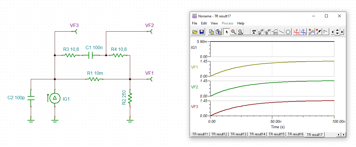
"I have successfully implemented my INA3221 circuit with the 250 ohm resistor as the DUT. My voltage datapoints for the DUT has a temporal resolution of 1Hz. When I graphed the DUT's voltage drop thru time, the graph is exponential which signifies that the bypass capacitor in between the IN+ and IN- pins has contributed a time constant (tau = R*C). When I tried computing the theoretical value of the R so that I can compute the tau, the theoretical tau I computed is pretty much too low to the experimental tau. I calculated the theoretical tau using Thevenin theorem so far. I do not know how else to compute the tau given the circuit I have. Can someone please help me calculate the tau of my circuit? I have tried checking INA3221 datasheet if it already has an equation for the tau as a function of DUT resistance and bypass capacitance, but it seems like it is not available.

Thank you very much.

  • Let me add a photo from my customer.

  • Hi Yanni,

    keep in mind that the nature of current source plays an enormeous role for computing the time constant. See what happens when the source capacitance of current source is changing:

    yanni_ina3221.TSC

    Kai

  • Hello valued engineer,

    So it seems that your measurements of the DUT resistor voltage with a volt-meter show some logarithmic behavior where voltage is taking some time to settle. Is my understanding on this correct? Data plots would be very helpful.

    Well any settling in the current due to the INA3221 should be very small. You could test this by simply removing the INA3221 input pins from the bus and re-test the settling time of the DUT voltage.

    One thing that could be happening is that the input voltage (VCM) of the INA3221 is changing as the DUT voltage rises. When the VCM of the device changes, it will increase its input bias currents (IB) according to Figure 12. As IB increases so will the input offset voltage due to the input resistors (10.8 Ohm resistors), which will result in some error that is increasing as DUT voltage is rising to final value.

    There could be other things going on too such as Volt-meter's drift with VCM or temperature, or the capacitance of the 5.9mA source (as Kai mentioned), or just parasitic capacitance on the PCB.

    Also keep in mind that the shunt voltage the INA3221 is sensing is very small and is impacted by offset error. The input offset error of the INA3221 is specified at +/-80uV maximum and the shunt voltage is 59uV, thus if the INA3221 measurements are not calibrated you could be reading very high error in the current measurement of INA3221.

    The best thing to do is simplify the circuit by removing the INA3221 (unless you are using it for data collection) and determine what the source's limitation are. You also may want to consider increasing the shunt resistor to improve INA3221 accuracy.

    Sincerely,

    Peter

  • RIGHT. I completely forgot that the current source has a capacitance. I ran along to check the datasheet of the current source (ADN8810) and I do not see any source capacitance. When you say source capacitance, do you mean an external bypass capacitor attached to the output pin of the current source? If yes, then I do NOT have any external bypass capacitor attached to the output pin of the current source. Please do correct me if I got something wrong.

  • Hi peter,
    Actually, there is no involved voltmeter when I gathered the datapoints for my dataplots. The voltage datapoints were sensed and collected by INA3221 themselves. Having said this, I don't think that removing INA3221 is an option. And yes I need to figure out the "settling time" of the voltage value of the DUT.

    For the VCM, I can assure you that the VCM is not changing in my experiment and my dataplots showed it doesn't. I do apologize for not sharing dataplots yet.

    For the offset error, I do believe that this will not be a concern to me since I am only interested with obtaining the VBUS (DUT resistor voltage) as sensed by INA3221. Please do correct me if I'm wrong in saying that current measurements aren't that of a concern when it comes to VBUS measurements.

    Why does increasing the shunt resistor improves INA3221 accuracy? Do you mean accuracy in current sensing or VBUS measurements?

    Thank you very much.

  • Hi Yanni,

    I think the exponentiality comes form the ADN8810 itself. This could have to do with the finite bandwidth of ADN8810. I can see a settling time of 3µs in the specifiactions. Also see figure 14. Any additional stray capacitance at the output of current source would furtherly increase the delay as simulated above. 

    Would be interesting to hear what time constant the customer sees :-)

    Kai

  • Hello customer,

    So we really need to simplify what is happening here. I believe the issue is that the DUT voltage (as sensed with INA3221 VBUS pin) has some long settling time. Correct?

    So what is this settling time approximately? What is the rise time? What is the step size of the current source (0mA to 5.9mA)? What is the rise time of the current source?

    According to the schematic provided, the bus voltage is the DUT voltage. So once current source turns on, the bus voltage goes from 0V to ~1.46V, As the INA3221 input voltage (VCM) changes, so do the input bias currents, which can create dynamic offset error that settles as VCM settles. See figure 12 of datasheet.

    The INA3221 front-end is essentially just an ADC so capacitive loading should be fairly low. The only way that this can be proved however is to remove the INA3221 or disconnect the electrical connections to source, and probe the DUT voltage with an oscilloscope that has BW much greater than the apparent settling time. Doing this will definitively prove what the true settling time of the system is. Then you can reconnect the INA3221 to compare how the device may change the settling time and accuracy.

    There could be other factors such as temperature and resistor temperature coefficients as well as temperature drift with the current source.

    Sincerely,

    Peter

  • "Hello Kai, how would you say that the finite bandwidth is culprit? Yup, I have read about the settling time of 3 µs but I figured that that settling time is for the ADN8810's op amp(?) itself. Correct me if I'm wrong but I don't think it should affect the time constant of my circuit??

    As for the time constant, based from the plots I have, the settling time of the DUT resistor voltage is ~12s. This ~12s should be about 5 times tau. So the tau, time constant, is about ~12/5s or 2.4s.

    This is why my current sitution is puzzling for me because the time constant is just too large. :("

  • "Yes, Peter, the DUT voltage (as sensed with INA3221 VBUS pin) is taking a long settling time. As for the time constant, based from the plots I have, the settling time of the DUT resistor voltage is ~12s. This ~12s should be about 5 times tau. So the tau, time constant, is about ~12/5s or 2.4s.

    Ithink the step size of the current source can be found in Fig. 14 of the current source's datasheet (ADN8810). It's in the microsecond level.

    Thank you for your suggested solution of using an oscilloscope! I will definitely do that part to investigate this situation of mine.

    Thanks!"

  • Hello,

    12 seconds is a long time for INA3221, but given that it is sensing such a small shunt voltage with an input filter as well, the circuit is far from its capabilities. As I mentioned, the device's input offset voltage is ±80µV and you are sensing a 59µV shunt voltage. In reality the input offset voltage could be worse given the input filter, which is generating a dynamic offset that changes with VCM, Vshunt, and temperature.

    All of this could result in a slowly changing/settling input offset error voltage.

    First thing though is to remove the INA3221, measure the DUT voltage directly with oscilloscope or ADC, and determine true settling time of circuit. Then connect INA3221 input pins back to the load line, and re-measure. Then potentially look into improving the accuracy of INA3221 by removing input filter, increasing shunt resistor, increasing conversion time, increasing number of average, and/or replacing INA3221 with another power monitor with smaller offset voltage if the shunt resistor cannot be increased anymore due to system constraints.

    I will wait for your updates.

    Best,

    Peter

  • I have opted to use INA226 instead of INA3221 for the voltage monitoring. A separate VBUS is a lot better than the IN- pin of INA3221. This should help with the bias current messing up the bus voltage reading. Thanks!

  • Using the INA226 over INA3221 can be beneficial since VBUS can be connected directly to bus (on the other side of the 10.8Ω input resistors) and thus not create larger input offset due to its own leakage current (VBUS/320kΩ). Overall, using an input filter with the INA226 is much better than with the INA3221 due to imbalance of IN+ and IN- bias currents.

    Please post back to the forum for any other questions.

    Sincerely,

    Peter