This thread has been locked.

If you have a related question, please click the "Ask a related question" button in the top right corner. The newly created question will be automatically linked to this question.

PGA309EVM-USB: After calibration is complete, EEPROM calibration data are all zeros

Part Number: PGA309EVM-USB

Hi Guys,

Greetings! Customer is using the PGA309EVM-USB.

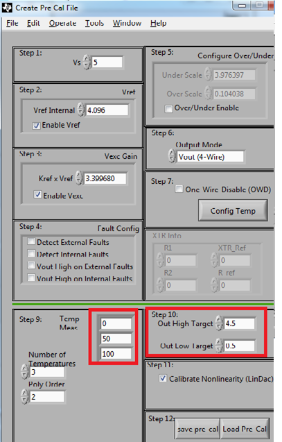
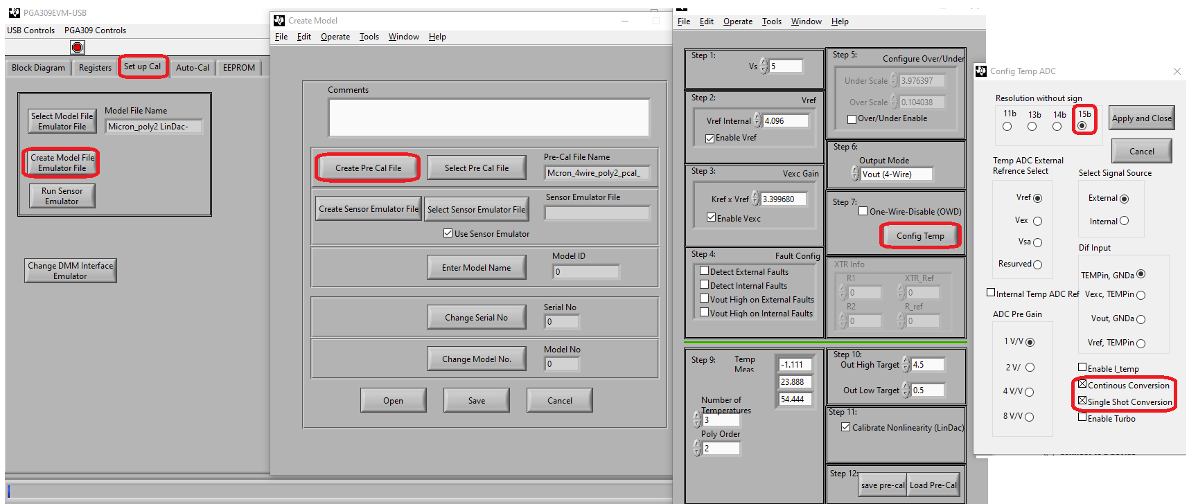
They proceed with the Auto calibration and the software shows all the necessary gain and offset adjustment on screen and claims the calibration is complete. When they go and look at the eeprom all the calibration data are zeros and the only emulator points where the output works correctly are at the last temperature point calibrated. They have reviewed the calibration data file generated by the program and it comes up with zeros in the 17 calibration points. All other functionality is fine.

They have verified that the "proj_PGA309EVM-USB" folder permissions are set to "Full control". Got the information from this link  https://e2e.ti.com/support/amplifiers/f/14/p/788283/2918447

They also verified this in the sub folders as well. The program is still placing zeros in all 17 of the offset and gain calibration points. Note that the calibration file is being created by the program and some of the settings are being written to the file, just not the calibration data.

So they believe the program has the necessary permissions?

Kindly help on this issue. Thank you. 

Best regards,

Jonathan

  • Hello Jonathan,

    I have not seen this problem before. I will need to investigate and get a hold of the PGA309EVM-USB to attempt to reproduce the issue. 

    Below is a power point presentation that shows the steps involved in setting up the PGA309EVM that you may find useful.

    6082.Calibration = USB_DAQ + PGA309EVM_updated (1).pptx

    1)  Kindly confirm that all the USB_DAQ controller jumpers at set on default position, and PGA309EVM board jumpers are set on default condition according to the mode of operation (voltage out 3-wire/4wire or current output) as documented on the power-point. Please also advise if this is a voltage out 4-wire, voltage out 3-wire or current output configuration.

    2)  Please provide / post the Pre Cal File, the sensor emulator file, and model file they are using in this case.

    3)  Please verify that on step 9, of "Create Pre Cal File" the correct number of temperatures are entered. 

    4)  After performing the calibration, please provide a snap shot of the PGA309EVM "Auto-Cal" tab of the GUI.  

    5)  On the post above, you have mentioned that the program is still placing zeros in all 17 of the offset and gain calibration points and mentioned the calibration file is being created by the program and some of the settings are being written to the file, just not the calibration data.  Can you confirm if any of  the EEPROM settings are changing each time you are running Auto-Cal? Please navigate to the "EEPROM" GUI tab, press the "Read EEPROM" button, and provide a snap shot of the EEPROM contents (GUI snapshot) read by the GUI.  

    Please allow a couple of days while I get access to the PGA309EVM-USB and kindly provide the files, GUI snap shots and information above.

    Luis

  • Luis,

    Thanks for reviewing my case. Here are my responses to your requests.

    1) I am using the 4wire mode. I have verified all jumpers are in the positions as shown in the powerpoint you have provided. The following exceptions are JMP14, JMP15. They are both in the 100m position. The output voltages of my particular sensor (silicon strain gauge) are much higher than the 10m range can provide. The 100m range is working well.

    2) All files loaded

    3) I have verified step 9 values. There are 3 values in the value field and 3 is the number of points. Note that while watching the process of calibration during its function I did indeed see the output of the emmulator go to the correct values. The emmulator is working quite well from what I've seen.

    4)

    5) I uploaded an Excel spreadsheet with multiple runs of the calibration data (Just the top portionthat has values) that has been generated with the attached model file. The data does look to be varying from run to run.  

     Cal comparison of some data 2_23_26_and 3_1.xlsx

    poly2_LinDac_MN_0_SN_5_DC_921.txt
    Fullscreen
    1
    2
    3
    4
    5
    6
    7
    8
    9
    10
    11
    12
    13
    14
    15
    16
    17
    18
    19
    20
    21
    22
    23
    24
    25
    26
    27
    28
    29
    30
    31
    32
    33
    34
    35
    36
    37
    38
    39
    40
    41
    42
    43
    44
    45
    46
    47
    48
    49
    50
    51
    52
    53
    54
    55
    56
    57
    58
    59
    60
    61
    62
    63
    64
    65
    66
    67
    [General Info]
    Date=3/1/2021
    Time="9:37 AM"
    [Paths]
    Model path="/C/Program Files (x86)/proj_PGA309EVM-USB/Model_Files/Micron_poly2 LinDac.txt"
    Pre-Cal path="/C/Program Files (x86)/proj_PGA309EVM-USB/Pre_Cal_Files/Mcron_4wire_poly2_w_LinDac.txt"
    Sensor Emulator path="/C/Program Files (x86)/proj_PGA309EVM-USB/Sensor_Emulator_Files/Micron_first_run.csv"
    [EEPROM Data]
    Addr0=21577
    Addr2=0
    Addr4=0
    Addr6=1495
    Addr8=4383
    Addr10=0
    Addr12=0
    Addr14=38080
    Addr16=0
    Addr18=7551
    Addr20=64923
    Addr22=0
    Addr24=0
    Addr26=0
    Addr28=0
    Addr30=0
    Addr32=0
    Addr34=0
    Addr36=0
    Addr38=0
    Addr40=0
    Addr42=0
    Addr44=0
    Addr46=0
    Addr48=0
    Addr50=0
    Addr52=0
    Addr54=0
    Addr56=0
    Addr58=0
    Addr60=0
    Addr62=0
    Addr64=0
    Addr66=0
    Addr68=0
    Addr70=0
    Addr72=0
    Addr74=0
    Addr76=0
    Addr78=0
    Addr80=0
    Addr82=0
    Addr84=0
    Addr86=0
    Addr88=0
    Addr90=0
    Addr92=0
    Addr94=0
    Addr96=0
    Addr98=0
    Addr100=0
    Addr102=0
    Addr104=0
    Addr106=0
    Addr108=0
    Addr110=0
    Addr112=0
    Addr114=0
    Addr116=0
    XXXXXXXXXXXXXXXXXXXXXXXXXXXXXXXXXXXXXXXXXXXXXXXXXX

  • Luis,

    It looks like the images and some of the files did not load. I will attempt to deliver a Requested screenshots 3_1_2021.zipdifferent way

  • Hello Joseph,

    I have received the model and Precal file along with the GUI snapshots.

    I will attempt to reproduce the issue in the Lab using the PGA309EVM.  Please allow a couple of business days.

    Thank you and Regards,

    Luis

  • Hello Joseph,

    I attempted running the PGA309EVM-USB using the Pre-Cal file, Model file and Sensor emulator file you are currently using on the set up.  I was able to reproduce the issue were the EEPROM look-up table is not filled.

    It appears the issue is related to the ADC temperature measurement settings of Register 6. While comparing the Pre-Cal file against other Pre-Cal file examples, the main difference was on the Register 6 settings, were all register settings are set to "0" on the Pre-Cal file on this setup.   

    Can you kindly modify the ADC temp setting to '15b’ resolution and select the "Continuous Conversion" and "Single Shot Conversion" ADC mode as shown below:

    You may access these settings by navigating to “Set up Cal” tab.

    Press the “Create Model File Emulator File”--> “Create Pre Cal File” --> On Step 7 of the “Create Pre Cal file” dialog press “Config Temp”.

    Select the ADC temp settings as shown on the image below:

    Alternatively, you may load the modified Pre-Cal file attached below, and verify if the device performs calibration properly.

    Mcron_4wire_poly2_pcal_mod3.txt
    Fullscreen
    1
    2
    3
    4
    5
    6
    7
    8
    9
    10
    11
    12
    13
    14
    15
    16
    17
    18
    19
    20
    21
    22
    23
    [PGA309_Settings]
    Numb Reg=3
    Poly Order=2
    Output Mode=0
    Vout_High_Target=4.500000
    Iout_High_Target=0.000000
    Iout_Low_Target=0.000000
    Vout_Low_Target=0.500000
    Vs=5.000000
    Vref=4.096000
    Calibrate Nonlin=TRUE
    Reg0=0
    Reg1=0
    Reg2=0
    Reg3=1280
    Reg4=0
    Reg5=0
    Reg6=5123
    Reg7=0
    Reg8=0
    Temp0=-1.111000
    Temp1=23.888000
    Temp2=54.444000
    XXXXXXXXXXXXXXXXXXXXXXXXXXXXXXXXXXXXXXXXXXXXXXXXXX

    I suspect that this is a software limitation on the EVM; I will need to investigate since I was not involved on the software development; but the EEPROM table fills properly after selecting these Temp ADC settings.

    Please let me know if the attached Pre-Cal file or modifying the ADC temp settings works for you.

    Thank you and Regards,

    Luis