This thread has been locked.

If you have a related question, please click the "Ask a related question" button in the top right corner. The newly created question will be automatically linked to this question.

LM7372: Failure of part in circuit when unpowered.

Part Number: LM7372
Other Parts Discussed in Thread: TPS62110

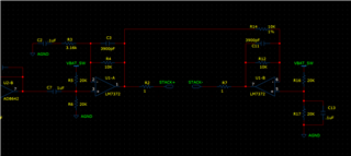
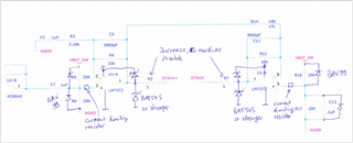
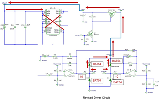
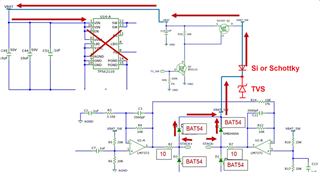
I am using the LM7372 to drive a piezoceramic stack. The stack is in parallel with an inductor so there is no way the stack can build up charge. However, we are seeing a significant number of failures of this chip. I suspect it is a latch up effect but  I am no familiar with diagnosing this failure. The LM7372 is not powered most of the time. It is switch off form the 15 volt batter by an FET. Also, most of the time the battery is disconnected from the circuitry. I did a simple ohm meter investigation of two failed chips and one new one. Here at the resistance value with respect to V- pin 4. 

Pin#     Name        Failure 1       Failure 2     New Chip

1          Out A         2.24K            132 ohms     20Meg

2          -INA           4.7meg         1.1K             47meg

3          +INA          520 ohms     4.8meg        17meg

5          +INB          2.7K              4.8meg        19meg

6          -INB           570 ohms     4.8meg         46meg

7          Out B         82 ohms       150 ohms     17Meg

8          V+             467ohms       111 ohms      34 meg

I suspect the failure could be latch up but not sure. Please help. I would really like to talk to someone on the phone or in Windows Teams. It would make the transfer of information much Quicker.

Thanks Don Kyle

972-418-3057

  • Hi Don,

    can you please post a schematic?

    Kai

  • Here is the basic schematic of the driver circuit. The power switching circuit is not shown. This device is only powered up for short intervals and the rest of the time it is unpowered. I hope you can see this image.

  • Hello Don,

      Thank you for sharing the schematic. What you described seems to match up a latch up failure. 1 ohm resistance does not seem enough in between amplifier and the piezoceramic stack. Also what is the power up sequence of the application? Are you powering amplifier before battery?

    Thank you,

    Sima

  • The input amplifier to the LM7372 is powered as soon as the device is powered up. Only the LM7372 is switched on during operation. The confirmation of this is Latch-up failure is what I initially need to know. So please everyone here comment. I have seen that a series signal diode from power ( in my case VBAT_SW ) might be a good solution. Does anyone have supporting info on this approach. Thanks!

  • Hello Don,

       A diode, more specifically a schottky diode would be best solution here. What is the voltage of VBAT_SW? Is it 15V? Also what are the supplies to the amplifier is single 15V or 15V/-15V?

    Thank you,
    SIma

  • The power supply is a single 15V.

  • Hello Don,

      With half of 15V at the input of the amplifier. There really should not be a problem there and the resistors are high enough so it isn't a current issue at the input as well. Would you be able to test the setup with the piezoceramic stack disconnected? At what point do you see the failure occurring?

    Thank you,

    Sima

  • The input will be a zero since the pullup is off of the VBAT_SW which is off as I stated earlier. Thanks for the help.

  • What is the output of the pre amplifier AD8643? I will have to run a simulation on this later today, but at the moment just checking for ways the ESD diodes internal to our amplifiers would break which would cause a short internally as well.

  • Normally the output is at zero. We put out a sinewave after we turn on the driver.

  • Hi Don,

    I would propose these modifications:

    Also, keep in mind that a capacitive load can mean an output short circuit at high frequencies. As a result too much output current could be demanded from the LM7372 finally damaging the LM7372 after some time.

    Kai

  • I would like to thank everyone for their input. I believe the use of the Schottky barrier diodes on the output will fix my problem. I run more tests and report back. Thanks!

  • Good luck Relaxed

    Kai

  • Thanks for the update; hopefully these diodes hold up with additional testing!

  • After implementing the four BAT54 and series resistors that was suggested this can protect the LM7372. However there is a problem. Connected to the VBAT line the feeds a TPS62110. Now the IC is blowing out!! It is basically shorted at the VBAT.

  • Kai's circuit is basically what I implemented. However, when I tested it unpowered the driver was protected but the dc to dc connect attached to the VBAT line a TPS62110 was blown up. Input shorted to ground. I suspect that the input voltage is going well above the 17 volt maximum of the chip. If I ground VBAT nothing is destroyed. Please let me know what you think.  Also, if I power the circuits with a power supply ( I have no batteries to try) it will also destroy the TPS62110. Thanks!

  • After implementing the four BAT54 and series resistors that was suggested this can protect the LM7372. However there is a problem. Connected to the VBAT line the feeds a TPS62110. Now the IC is blowing out!! It is basically shorted at the VBAT.

  • Hi Don,

    you could do it this way:

    Kai

  • Kai - Thanks for the reply. Would the BAT54 work for the Schotky? Could you suggest a TVS that would work? What would be the clamping voltage? Can someone explan to me the failure mechanism of the TPS62110? Thanks!

  • Hi Don,

    I would take the SMCJ15A, best from ST.com because of its very low leakage current and sharp knee.

    And for the Schottky I would go for the B140, SS14 or similar. For low forward voltage drop you should take a 1A Schottky here.

    Connect a 2k2 resistor from the anode of this Schottky to GND to allow leakage current flow.

    And you should have the TVS close to the supply voltage decoupling cap of LM7372. You already have a decoupling cap at the LM7372, right?

    Kai

  • Thanks for the suggestions Kai! I do have a decoupling capacitor on the LM7372. Getting the TVS close to the decoupling cap might be difficult. The resistor (2k2) is a 2000 ohm resistor? This will cause a significant addition to the current draw. Could I use a 20,000 ohm resistor?