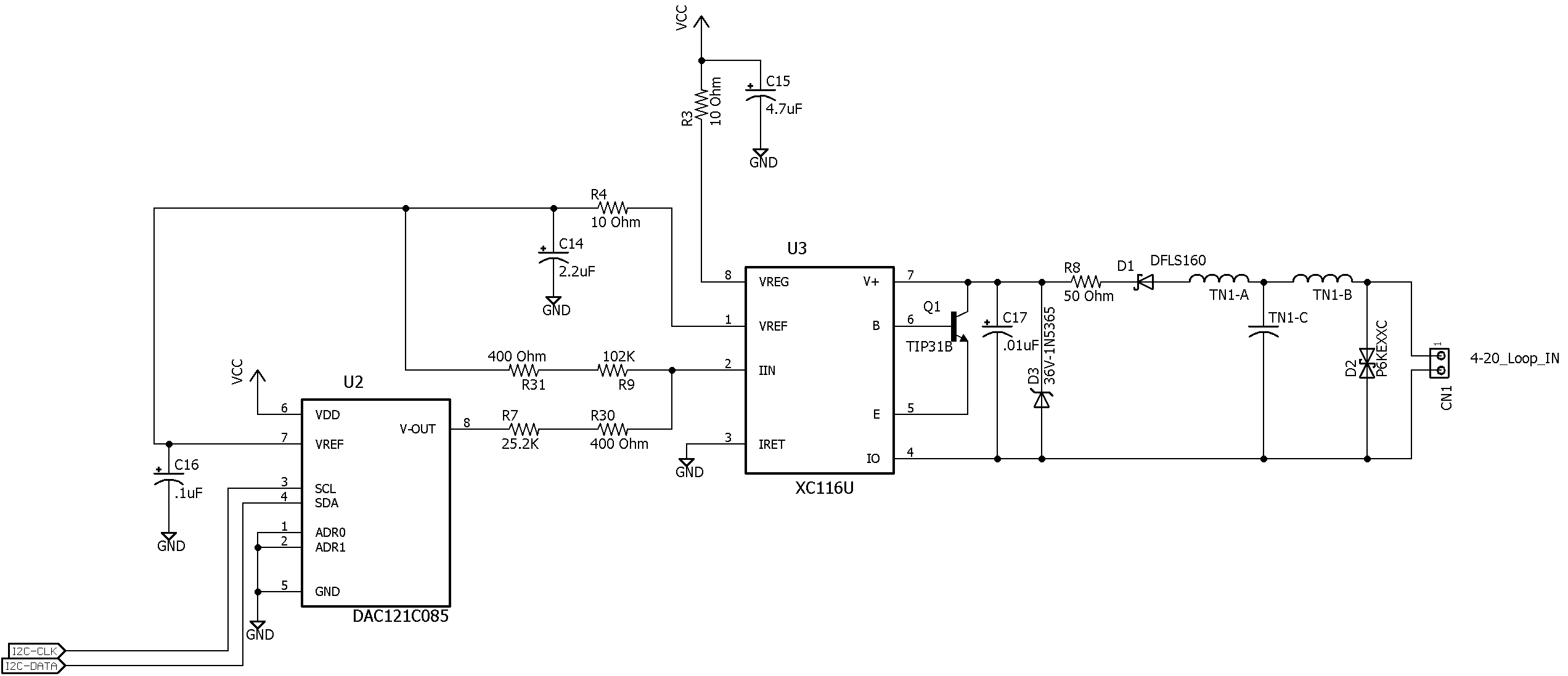
This thread has been locked.

If you have a related question, please click the "Ask a related question" button in the top right corner. The newly created question will be automatically linked to this question.

XTR116: XTR116 Power Up Issue

Part Number: XTR116

The schematic above shows what we hope is the relevant portion of our design. A few comments on the design:

1. It is a loop powered device with a PIC 18F ucontroller driving the DAC. Total current draw from the Vreg output is about 1.5 mA.

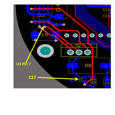
2. The Vref out of the XTR116 is connected as shown above, and goes nowhere else. The compensation for the capacitance on the line is as shown above, and there is no additional capacitance on the line, other than stray capacitance. The board layout is very tight in the area around and between the DAC and XTR116.

3. The Vreg line drives the 4.7uF cap shown on the schematic and another 1.5uF of distributed decoupling capacitors. In addition, the PIC has an internal regulator which is active in this design, and requires an external 10uF cap, which is connected to the PIC.

4. The "T" filter on the 4-20 mA input is an off-the-shelf EMI filter from TDK, part number ACH32C-333-T.

Our issue is as follows:

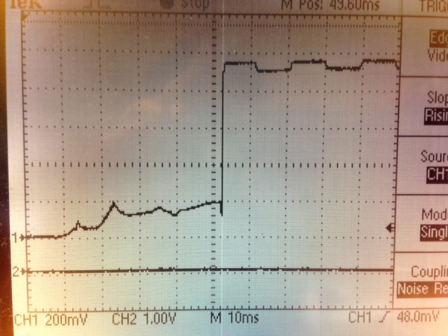
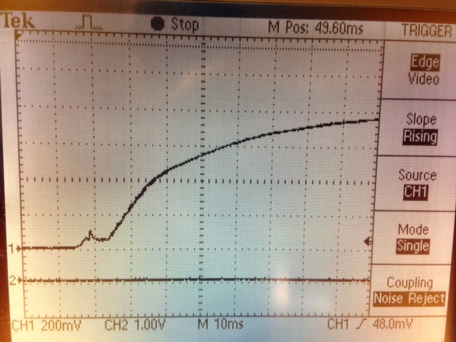
1. Upon applying power to the 4-20 mA loop (lab power supply set to 18 VDC with ammeter in series, but nothing else), the Vreg output goes to about 1.5 VDC and stays there. Both the Vreg and Vref outputs appear to be in current limit, with the 4-20 mA loop current going to 28 to 29 mA. This is easily repeatable, and occurs even if the PIC's reset is held active (PIC reset).

2. If the power is cycled quickly (from on to off back to on), the Vreg and Vref outputs attain their proper levels and everything functions as expected.

3. If power is turned off for a few seconds, the issue presents itself again.

Our thinking has been to increase the value of R3, but did not find much specific guidance on this during the initial design phase. We are early in our debug stage, but would appreciate any input we can get.

Thanks in advance,

Joaquin

  • Hello Joaquin,

    Could you prove the B pin of the XTR device with an oscilloscope during the conditions where the issue is occurring? If you increase the C17 capacitor to 0.1uF or 1uF does the issue go away?
  • Hi Collin,

    Thanks for the reply. Good suggestion regarding the input cap. Unfortunately, I am traveling and will not return to my office until next Saturday (2/18). I will get back to you once I have time to do some more work on this, likely sometime next weekend.

    Thanks again,

    Joaquin

  • Hi Collin,

    I had a chance to do some work on this today. Increasing C17  even to 1uF does not appear to eliminate the issue. I probed pin 6 with a scope, as you suggested. The first image below shows the trace on a normal power-up (draws 4 mA from loop), while the second shows the trace on a failed power-up (draws ~27 mA from loop, with both Vreg and Vref going into current limit).

    Again, I appreciate your help with this.

    Joaquin

  • Thanks for the additional information, we're looking into this. We have a few more questions to help us debug the issue. First, did you mean that the top image shows the system having issues whereas the bottom image is normal operation?

    -Is the C17 capacitor located physically close to an d on the same PCB as the XTR device?

    -Does the issue occur if the C14 and C15 capacitors are removed? If there is additional capacitance on the VREG and VREF lines that's not shown in the your schematic please remove those capacitors as well just for debug purposes and let us know the results.
  • Hi Collin,

    Thanks for the reply. Here is the additional information you requested:

    1. The photos were properly identified in my post: The top photo shows what occurs when the unit powers up properly, while the bottom photo shows the unit when it goes into what we are calling current limit mode. To clarify, when the unit goes into "current limit mode" (fails to power up properly), the waveform resembles an RC network waveform.

    2. The C17 cap is approximately 1" away from the XTR116. While this was a bit of a concern for us when we went for layout, we had other areas that we felt were more sensitive, and prioritized those above the C17 cap. When we looked at the layout, we thought that, while not ideal, the cap was ok where it was. In any case, when you cam back with the suggestion to increase the value of C17, the first thing that popped in our mind was the location of C17. When we tried the different values, we did so by installing the caps directly across the XTR116 pins. As mentioned earlier, that did not appear to have any impact on the operation. For reference, I include a shot of the board layout in the affected area (see below), showing C17, U# (XTR116), and the interconnect. But, again, we feel we have ruled this out as a possible issue, given what we have already done.

    3. As far as capacitance on Vreg, I'll clarify what I noted in my original post: The PIC ucontroller has an internal regulator, which we have enabled in this design (in order to avoid an external regulator, since the PIC's core can't handle 5V). That regulator requires an external capacitor for stability, and Microchip recommends a 10 uF cap, which is what we are using. That cap is not hung directly on the Vreg line, but somewhere downstream, in the PIC's regulator circuitry. We have the 4.7uF C15, as well as numerous decouplers that are hanging directly on the Vreg line (actually, downstream of the 10 Ohm R3). The total of the decouplers is about another 1uF. There is no other capacitance on the Vreg line, other than strays. Now, to your question: if we remove only C15 (the 4.7uF cap), the problem persists. If we remove only the PIC's 10uF stabalization cap, the problem occurs less often, but still occurs. If we remove BOTH the 4.7uF C15 and the PIC's 10uF cap, the problem appears to go away. This is consistent with our initial theory that the XTR's Vreg output can't handle the power-up surge current and goes into some sort of current limit. This theory appears to be supported by the fact that, if power is cycled quickly, the unit generally comes up properly. 

    Hope this helps. Look forward to your feedback, and we appreciate your help.

    Joaquin