This thread has been locked.

If you have a related question, please click the "Ask a related question" button in the top right corner. The newly created question will be automatically linked to this question.

TL084: TL084

Part Number: TL084

hi,

The TL084 is mainly used as differential amplification and precision full-wave rectification. See the figure below:
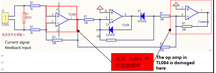
          

The front end of terminal CON2 is input with a voltage signal after the current transformer is converted;
When the current transformer is subjected to a voltage test, the TL084 chip is occasionally damaged;

Current transformers are used as follows: Two yellow BVR mini wires are connected to CON2 terminal block
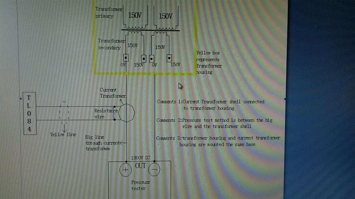
Withstand voltage test method: 1800V DC withstand voltage test of the casing with a large wire passing through the middle of the current transformer


I suspect there is a spike passing through the BVR yellow wire to the CON2 terminal of the board, which will damage the TL084 pin!

  • Eric,

    I agree that there is is a leakage or electric arc transfer from the test pulse into the TL084.
    I am mystified about the purpose of the thin black serpentine wire that shorts the two yellow wires.
  • Hi Ron,

    the black serpentine could be the shunt RES2. The black looks like heat shrink tubing containing a piece of resistance wire made of constantan...

    Kai

  • Kia,

    Good catch, There are creases in the material supporting your heat shrink observation. I didn't notice those creases previously.
    The wire/resistor is also another path for the leakage to flow as it appears to be close to the main cable through the center.
  • 1、Thank you very much for your support,But in order to solve the problem, you need to further help your company!

    2、At present, I also think that during the voltage test, there is indeed an unknown high-voltage pulse signal flowing through the BVR yellow line to the motherboard TL084,but is it uncertain whether the source of the high-voltage pulse signal is magnetic field interference or something else?

    3、The schematic diagram of withstand voltage test is as follows, I hope your company will continue to help us to explore the source of high-voltage pulse signal.

    4、

    In addition, I specifically use the oscilloscope to measure the current transformer between the two terminals (illustrated resistance wire ends) whether there is a pulse signal, after repeated measurements, and did not find high-voltage pulse signal;
    In doubt, it is possible that I did not find a pulse that damaged the pin of the chip during the test. In other words, this kind of pulse signal appeared randomly.

  • Hi Scott,

    voltage arcing can be a random process like lightning flashes during a storm. In your case air humidity can play an inportant role.

    From the rule of thumb that 1mm air insullates against 1kV the arcing must come from something which is very close (about 2mm) to the wiring which goes to the TL084. If you look carefully at your foto you will see that the resistance wire is almost touching the high current wire which is running through the hole of current transformer. So, the remedy is very simple: Increase the distance between the resistance wire/yellow wire and the high current wire which is running through the hole of current transformer. Bend the resistance wire away from the hole. Bend it towards the chassis.

    You could additionally take a small aluminium plate to shield the high current wire from the TL084 wiring. But keep this aluminium plate well away from the hole of current transformer and from the high current wire. Connect the aluminium plate to the chassis ground, right there where the current transformer is screwed on. It should cover most of the TL084 wiring.

    Kai

  • Thank you very much for your help. If you have questions, continue to consult with you