This thread has been locked.
If you have a related question, please click the "Ask a related question" button in the top right corner. The newly created question will be automatically linked to this question.
Hello,
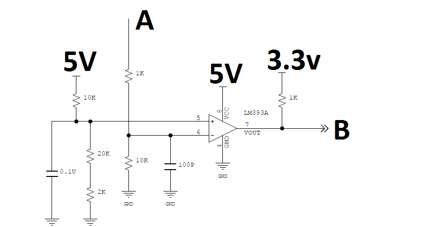
I am using LM393 IC in one of our designs. Vref (3.43V) is connected to +Ve terminal of comparator. Attached reference schematics and voltage wave forms at -Ve terminal (A) and comparator output (B). Can you please explain why comparator output start raising towards 5V and then starts falling.
Hi Kai,
Thanks for quick reply. We have a current transducer. Output of current transducer is given at point A in attached schematics. Pink color graph shows input signal to current transducer. Ideally, when pink color graph reaches above 1V ( it shows short circuit current in board is 50A), comparator output shall go to GND. but it is not going like that. It starts raising towards 5V from 3.3V then falling towards 0. Output of comparator is given to FPGA in our design. Kindly let me know if you need more information.
As comparator output is pulled up to 3.3V, so output voltage is at 3.3V until V- voltage raises above Vref. But, What could be the reason for comparator output to change from 3.3V to 5V then falling ?.
As comparator has open collector inside, not sure how output reaches to 5V.
Output at open collector shall be either open circuit or GND,No relation with VCC.
Thanks & Regards
Ganapathi
Hi Ganapathi,
hhm, 50A short circuit current is quite a bit. It could shift the ground potentials somewhere. This shift could be superimposed to your measurement. Have you connected the ground tip of scope probe directly to pin 4 of LM393A?
Kai
Hi Kai,
I have measured voltages just near the comparator. Everything seems OK. May be during my last measurements, ground might have shifted and its super imposed on comparator outputs. Pink wave form is t +Ve terminal, Blue waveform is at -Ve terminal and Yellow waveform is comparator output. Thanks a lot for your quick responses.
Thanks
Ganapathi
Hi Kai,
VCC is 5V and Common mode voltage range is 3V in my design. So does it mean that if V- reaches to VCC (5V in my design) and V+ can be at 3V max ?
Thanks
Ganapathi