This thread has been locked.

If you have a related question, please click the "Ask a related question" button in the top right corner. The newly created question will be automatically linked to this question.

INA223: Output Impedance

Part Number: INA223

Hi Sir


According to table in Page 4, output impedance of INA223 is 4 ohm typically

Since it names as impedance, should it be AC term?

I cannot find any description more in the datasheet.

Is it possible to take a measurement to confirm?

How should I do?


Thanks

Regards

Ben


  • Hi Ben,

    this should be the Ron of output mux. You can measure it indirectly by connecting varying loads to the output. The output resistance forms a voltage divider with the load resistance and when varying the load resistance the output voltage will also vary. From this change you can calculate the output resistance. Don't take too small load resistances, though, to prevent the output from saturating.

    Another method is to inject a current of 100µAp into the output and measure the output voltage. When using a sine of varying frequency you can obtain the frequency response of output impedance.

    Kai
  • Hello Ben,
    That 4 ohm value corresponds to the DC impedance and we currently to do not have the AC impedance characterization curve. To obtain that curve, you can use one of the methods described by Kai above.
  • Hi Kai

    Thanks for guidance!

    To more accurate output impedance calculation, approximate load to 4 ohm is required

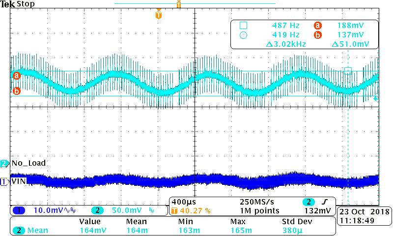
    For avoiding overdriving (I am referring to Fig 22 “ Output Voltage Swing VS. Output Current), I set DC + AC across IN+ and IN- to get the waveform of No Load (Swing = 51mV as cursor, mean = 164mV)

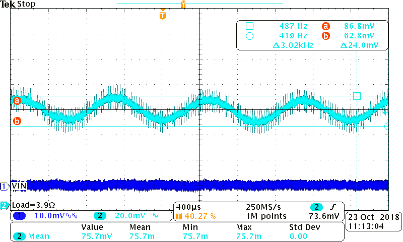
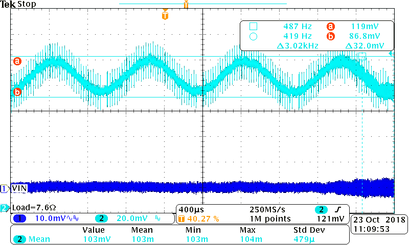
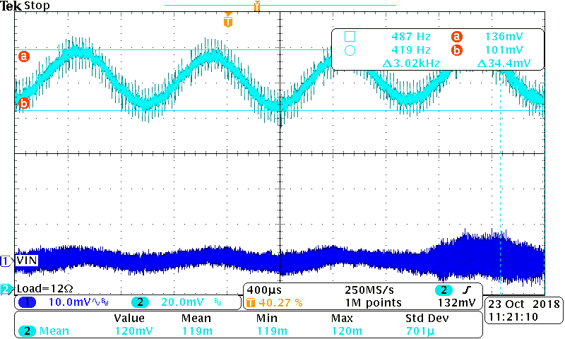
    And connect different loads to output, 3.9 ohm, 7.6 ohm and 12 ohm respectively, gaining the corresponding waveforms as well

    After calculation

    VOUT @ Load = VOUT @ No Load x (RL / (RL + RO))

    According to mean and swing of each Pics, RO is about 4 ohm

    I am curious what the spurs on the output waveform are, is that chopping frequency of INA223? or is there anything accidentally picking up?

    Could you please help to confirm the chopping frequency?

    I am trying to inject a current by another voltage source, the stimulus is DC source only this time, but the calculated R = VOUT / I is much bigger than expected 4 ohm typically!

    Thanks for comment!

    Regards

    Ben

  • Hi Ben,

    the spikes could be ground bounce resulting from the digital signals at the SCL and SDA pins.

    I would inject a sine current into the output. Take a sine generator with 1Vp signal amplitude and inject a current of about 1mAp via an 1k resistor. AC couple the sine by using a suited coupling capacitance (10µF, or so) in series with the 1k resistor.

    Kai
  • Hello Ben,

    Do you still need support on this thread?