This thread has been locked.

If you have a related question, please click the "Ask a related question" button in the top right corner. The newly created question will be automatically linked to this question.

INA122: Current Sense circuit for range 1uA to 300mA on 3V power rail.

Part Number: INA122
Other Parts Discussed in Thread: LOG114, OPA388, TINA-TI

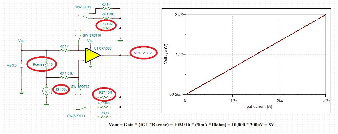
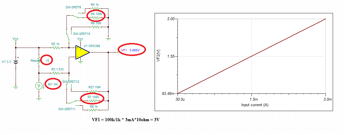
I am looking for a solution to measure the wide current range from 1uA to 300mA on a 3V rail. If it not possible to do for such high range and precision, we can further split this in two and use two amplifiers 1uA - 100uA & 1mA to 300mA. I tried and refer other but bias current and the differential voltage at the port (V drop not expected more than 0.05V on 3V rail) was the area I doubt. Please suggest. The output voltage after amplifier will be input to 3.3V ADC to read the current value.

  • Can you provide a sketch of what you are trying to accomplish? Is this a high side current sense like a resistor tied to +3.3V and the load tied to the other end of the resistor as a high side current sense for a device under test?
  • Hello Tim,

    Yes, High side current I want to measure. The concept will be to get the drop in power across Rsense through om-amp (CSA) to the ADC. 

    Please find the diagram as attached,

    Image result for high side current sense circuit

  • Tushar,

    We have LOG114 capable to measure Eight Decades, 100pA to 10mA, of input current but anything above 10mA will require a discrete solution.  Therefore, in order to measure the input current, IG1, of 1uA to 0.3A covering 6 decades in magnitude variation with any degree of precision will require at least three different gain stages and calibration of the initial error coming from the input voltage offset and gain error (mismatched resistors).  

    On Vs=3.3V supply, the highest shunt resistor, Rsense, you may use is 10ohm so for 300mA input current the input differential voltage is Vindiff=0.3A*10ohm=3V.

    Also, since the output of an op amp cannot swing all the way to negative rail, in order to be able to measure 1uA input current (Vout = 1uA*10ohm = 10uV), you must offset the output at least +50mV above the negative rail - this is accomplished by introducing a small mismatch in R3 input resistor - see below.

    For the IG1 of 0uA and matched R2, R3 resistors, the output swing should be 0V but VF1 is at 37mV due to output swing limitation. Introducing a small resistor mismatch in R3, lifts the VF2 to 60mV for the zero input current, within OPA388 output voltage linear range.

    Below please find the DC sweeps covering six decades of the input current, IG1, variations:

    I also attached Tina-TI schematic for your own simulations.

    Tushar high-side measurement.TSC

  • Tushar

    We haven't heard back from you so we assume this answered your question. If you need additional help just post another reply below.

    Thanks
    Dennis