This thread has been locked.

If you have a related question, please click the "Ask a related question" button in the top right corner. The newly created question will be automatically linked to this question.

INA2321: INA2321 common mode range vs REF voltage

Part Number: INA2321
Other Parts Discussed in Thread: INA321, INA2331
Hello,
I'm developping a product that will use two pressure gauges connected to each amplifier of an INA2321 (or 2331 if results are too slow).
I choosed this amp because I have very high low power constraints, and it features a sleep mode. I will wake it up 2000 times in a second and start performing measurements 10-20µs approx after waking it up, and then return to sleep.
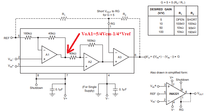
The gauge is resistive so it matches perfectly the Figure 2 of the datasheet.
Power supply for amplifier and gauge is 2.8V. So Vcm will be 1.4V (+/-5% max I guess).
The final gain will be between 10 and 20, still not determined.
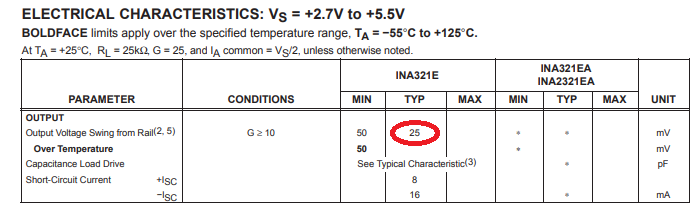
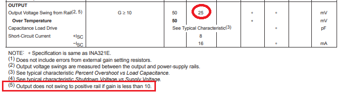
High precision is not required (1% is ok, or even 5%...), because I need to make detection, not precise measurement, but I need low power and fast amplifier. So I guess that with INA2321 I will achieve my timings, even if I start the measurements before the output voltage is fully stabilized very close to final value (0.1% or 0.01%, useless for me).
I will mainly use the gauge in one way of detection (say positive way). The negative difference is not very relevant for me in term of measurement, but I still need to go in the negative range to detect drift variations of the sensor, offset, atmospheric variation, etc.. I will drive the REF pin of each amp by 2 microcontroller DAC output buffered with a low power amp. I will set the REF voltage in order to get a zero output value at approx 0.3V when the gauge is not pressured. The REF voltage will be determined by software in order to keep the idle output voltage around 0.3V. I have not yet calculated the REF voltage range required by my application, but I think it could go up to 1V.
My question :
I have some doubt about the explanations given about the REF level and the input common voltage range.
I read the the Vcm max is Vs-1.2V, so 1.6V in my case, higher than my Vcm, so it's ok.
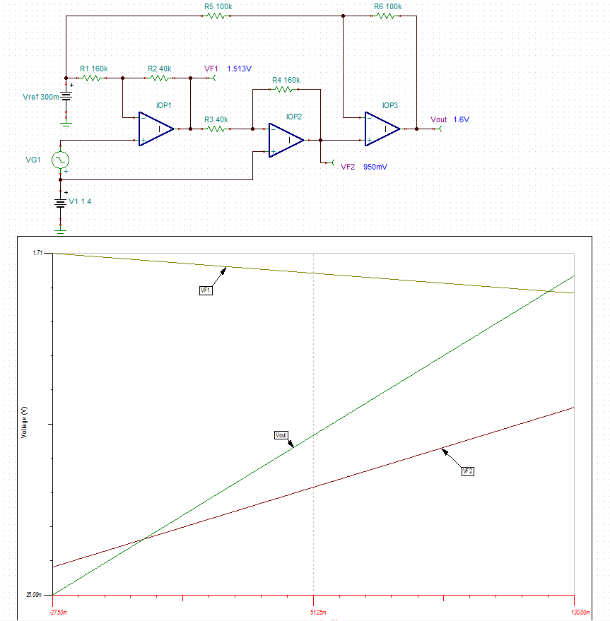
But I don't understand the Common voltage vs Reference voltage characteristic and the formula Voa1= Vcm*5/4 - Vref/4.
Could you please tell me how it can affect my circuit ? In my case the Vcm will always equal to Vs/2 +/-5%.
My other question : if input positive difference is too high (overpressure) can you confirm that the output will saturate at Vs=2.8V and does not fall down to Vss or any irrelevant level ?
Thanks
Aurelien
  • Aurelien,

    As you correctly stated the input common-mode voltage range of INA321 is from (V-)+0.35V up to (V+)-1.2V,  thus for Vs=2.8V supply it means Vcm_max=1.6V; however,  the upper and lower limit of the input range are bounded by the output swing of amplifier A1, and for the gain of 5 is a function of the reference voltage according to the following equation: VOA1 = 5/4 VCM — 1/4 VREF - see below. 

    In your specific case, where you use a gain of 10 or higher, you do not need to worry about violating these limits.   For your conditions, with INA321 supply of Vs=2.8V in gain of 10, the valid input differential voltage range is form -27.5mV up to +130mV - see below.

    Please download a free Vcm vs Vout calculator for instrumentation ampliers: 

  • Thank you for your fast reply.

    I will check with simulation, sorry I did not think about that.

    I take some holidays now, I will resume project at my return.

  • Hi,

    I've downloaded the vcm calculator, that's ok for Vcm with my config.

    But I don't understand the output voltage min and max (Vout min and Vout max) shown on the right. I see that max output voltage is fixed at 1.6V, is it the absolute output voltage (why saturation at 1.6V ?) or the output voltage referenced to REF signal (why cannot go below 25mV) ???

    Thanks

    Aurelien

  • Aurelien,

    What causes Vout vs Vin limitations in instrumentation amplifers has to do with the voltage range limitations of the internal nodes (see VF1 and VF2 below), which are function of supply voltage, gain, reference and input common-mode voltage.

    What limits INA321 upper range of Vout at 1.6V (Vout=Vref+gain*Vin_diff=0.3+10*0.13) is VF2 linearity while on the low side minimum voltage of 25mV comes from the output swing limitation of the output op amp (no op amp output may swing all the way to its rail) - see below.

  • Hello,
    I made my first tests with INA2331. Two comments, and I believe they are important :

    1. Vout limit
    You told me the output would saturate at 1.6V, but this is not what I see...
    I have set Vref @ ~0.5V. I see that the output can rise linearly up to ~Vcc (2.8V in my case).

    Some examples of measurement (VREF=0.510V constant, and gain ~ 10)
    Vin(diff) = 12.27mV => Vout = 0.634V (ok)
    Vin(diff) = 49.01mV => Vout = 1.003V (ok)
    Vin(diff) = 142mV => Vout = 1.933V (ok)
    Vin(diff) = 212mV => Vout = 2.640V (ok again)

    2. Shutdown to active state
    On the datasheet, there is a graph "SHUTDOWN TRANSCIENT BEHAVIOR" that shows that the output is set up within less than 20µs. But in my case, I measure 150µs.

    When not toggling amplifier on/off between my measurement, the output stabilization time when I turn on my sensor is lower than 10µs (5µs for INA2331 stabilization + 5µs for REF stabilization from DAC followed by a 1MHz buffer amplifier). If I toggle the INA2331 off after measurement and turn it on before measurement (at same time with sensor power on and DAC REF enabling), then the stabilization time is 150µs !
    For this measurement, Vref = 0.510V and Vin(diff) = -3.75mV, with gain = 10 (when output is stabilized, I measure 0.472V).

    First screenshot without sleep mode (green = sensor power ; blue = Vref ; yellow = output)

    And with sleep mode enabled :

    Explanations are welcome :)

    Thanks
    Aurelien

  • Our Instrumentation amplifier Vout vs Vcm tool has an error, which improperly limits the Vout swing from positive rail for gain 10 and greater - this suppose to happen only for gains less than 10 - see below.  Thank you for bringing this to our attention. 

    For gain of 10 like in your case,  the output typically should swing within 25mV of either rail.

    Shutdown to active mode refers to using an enable pin but your screen shots seem to show power up/down condition - these are two completely different events. Having said that, the only timing specs in the datasheet specify settling time and overload recovery time - see below.

  • Hello Marek,
    For the sleep mode condition, I do use the ENABLE pin. The INA2331 power supply is stable, only the sensor power and the DAC (VREF driving) are disabled during sleep. That's why I'm perturbed by my observations !

    Aurelien
  • Aurelien,

    The Shutdown Transient Behavior graph shown in the datasheet assumes the output is driven at all time within INA2321 linear range and only Vsd is toggled. However, in your case you also have sensor and DAC reference disabled, which initially causing the output to saturate against its positive rail (see below) before overload recovery occurs.

    This is completely different condition than the one shown in the graph below. If you want to duplicate the timing, you must keep sensor and reference alive while toggling only Vsd pin of INA2321.

  • Hello,

    Can you explan why I have a so long restoration delay after saturation in this case ? We're talking about 100µs at max output, then it falls slowly during 70µs, then a new saturation and then the output becomes instantaneously correct.

    We are not talking about  a small time difference here, between normal mode and sleep cycled mode...

    Best regards

    Aurelien

  • Once you allow the output stage of INA2321 to operate in a non-linear region, the overload recovery time may vary greatly depending on exact circuit conditions like gain, amount of overdrive, temperature, process variation, load (what do you drive?), etc. For that reason, you should make sure the sensor power and reference voltage is turned on first and operate linearly BEFORE toggling enable pin of INA2321 in order to prevent its output from being driven to the rail, which causes a long recovery time.
  • Hi,
    I have replaced the INA2331 by INA2321, things are much better :
    - I don't have the saturation behavior at the output anymore (in fact, now I have a better response when leaving sleep mode rather than keeping the INA powered)
    - the output is 2x or even 3x less noisy

    The lower slew rate is still valid for my application, so I think I will continue my test with this reference now...

    Aurelien