This thread has been locked.
If you have a related question, please click the "Ask a related question" button in the top right corner. The newly created question will be automatically linked to this question.
Hello,
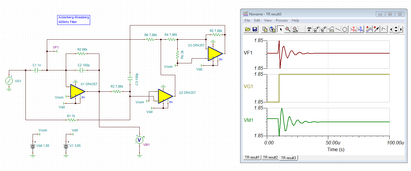
I'm trying to replicate Åckerberg-Mossberg Filter using OPA357. With the SNAA287A as reference, how can I get 400kHz center frequency?
The selected values are:
R4=R5=R3=R6=4.3K
C2=C3=91pF
C1=1nF
R1=6.8K
R2=66K
Rout1=1.5K
Rout2=8.2K
Cout1=2.7nF
Rc=2K
I'm not sure I got all values right. Any comments/suggestions?
Thanks!
That is a really interesting filter Roman,
I had not see this before so I set up in TINA to play with it, the analysis word file is here with the TINA file below, My V11 TINA supports MonteCarlo so I ran your design using 1% C and 0.5% R (a recent thread, we found C0G C's in 1% to be <$0.01.
You might want to try this with the lower noise and power OPA837.
And actually, the true one pole GBP is what you want for comparing active filter solutions - THe OPA357 is 120Mhz in TINA model (100Mhz in PDS), the OPA837 is 50MHz in both - so about 1/2 the speed,. I tried dropping in the OPA837 into the TINA sim, does not find a good DC point for some reason.
Hi Michael,
Thank you for your great work creating TINA model.
The interesting point here mentioned, I should check tolerances for my passive components.
You bet, that discussion on cap tolerances was not in e2e, but an email discussion I was having, here is a copy,
the 1% COG caps are what you want to use,
Ok guys.
I built a prototype now with 0.1% resistors and 1% capacitors, still centered on 400kHz, with no luck.
I used another values (because of availability in 0603 size), see the schematics:
I still got the amplifiers unbalanced, so they're triggered to Vdd +- on their outs.
My input is perfectly balanced to Vcom,
And straight after C1 it got DC shift:
And the signal on U1 out (no signal):
I tested op amps alone each, they are working perfectly.
Any ideas?
Hello Kai,
This is an exact schematics suggested in SNAA284 and snaa287a. So what do you mean by this? What should I check or fix?
Thanks
Hi Roman,
I think there is a mistake in your simulation. You have swapped the input pins of U2:
Kai
Hello Kai!
Interesting find, thanks!
I used the TSC file created by Michael Steffes as reference. I will double check my actual schematics in a week when I return to office.
Ok, found the source of mistake: the old revision of snaa284 with the same mistake in schematics, it was corrected in snaa284a later.