This thread has been locked.

If you have a related question, please click the "Ask a related question" button in the top right corner. The newly created question will be automatically linked to this question.

INA128: seeing output dip with square wave input

Part Number: INA128
Other Parts Discussed in Thread: ISO224, BUF634

Hi,

I'm seeing some strange behavior at the output of INA128 and I was hoping that someone could help identify what might be going wrong.

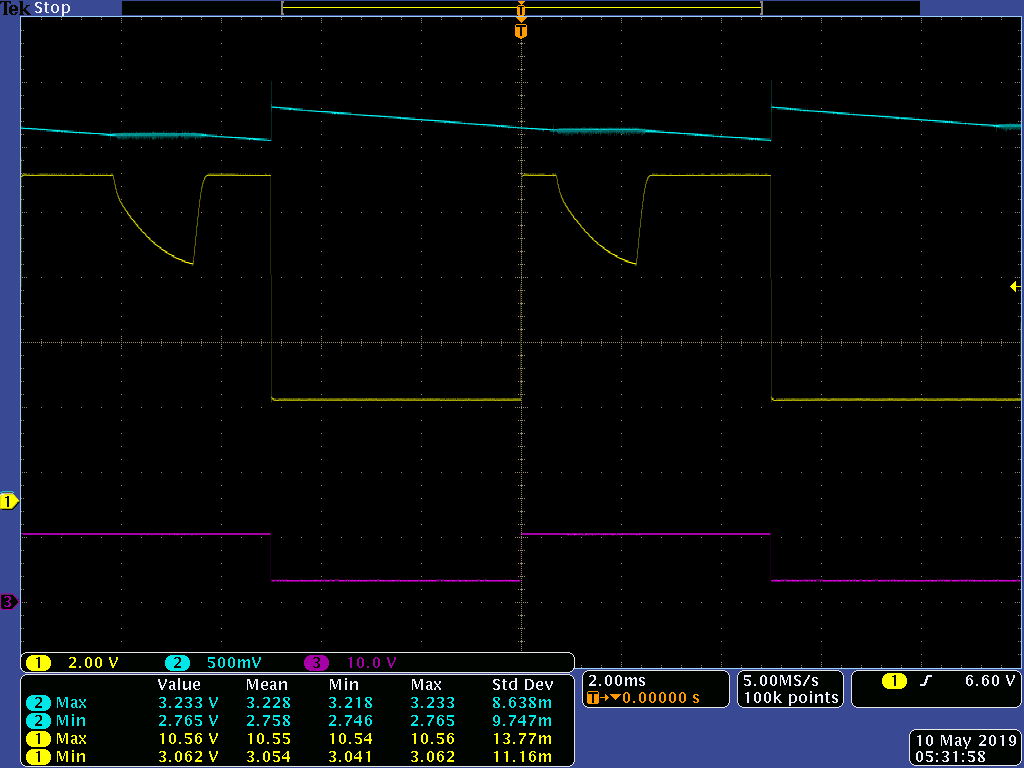
The input, shown in magenta, is a roughly 3-10 V square wave input @ 50% duty cycle. My INA128 has no gain resistor, so it's programmed for unity gain. You can see that the output of the amplifier (yellow, ch. 1) basically supports that, as it's shown to be 3-10.5. However, during the high portions of the square wave, the output of the amplifier collapses for a short while for whatever reason. This is especially problematic for my application because I have a falling edge detector on the output of INA128, and this output is causing a false falling edge trigger.

Regards,

Michael

  • Hi Michael,

    can you show a schematic?

    Kai
  • Hi Kai,

    I don't have a local copy of the schematic on me, but you can find it on this E2E post of mine if you search for "sense_mini."

    Also, note that the gain resistor is not populated and that R2 shown in the first image has been changed to a 301k resistor to divide the input down into the range of the multivibrator.

    -- Michael

  • Hi Michael,

    I cannot find the INA128 there.

    Kai
  • INA128 is the amplifier at the very beginning of the portion labeled “Measurement,” or U1.
  • Hi Michael,

    there are several issues:

    1. It's no good idea to power analog electronics with a switcher without any low pass filtering at the output of switcher. Analog chips need clean, stable and noisefree supply voltages. A switcher, on the other hand, produces lots of ripple and HF noise. Are the +/-12V supply voltages, especially the +12V supply voltage, stable at all?

    2. I would remove C7. Such a high load capacitance at the output of INA128 can make the INA128 instable.

    3. Why are you using the BUF634 between the INA128 and ISO224? As the BUF634 is way too fast at this place, this looks like total overkill.

    Kai

  • Hi Kai,

    1. Edit: I have not checked the 12 V supplies on a scope yet, I will be doing that today.
    2. C7 is the "hold" part of a sample and hold circuit. On the falling edge of the output of INA128, the monostable multivibrator closes the switch for ~15 us and charges C7. The switch is then immediately opened. C7 is sized so that the voltage across the cap (the target is roughly 3 V) doesn't discharge much of its voltage during a 1/550 Hz period based on the leakage current spec of MAX4648 and the input bias current spec of BUF634.
      1. It seems that INA128's max load capacitance stability on the datasheet is 1 nF. Do you think that this is causing the dips in the output voltage? What do you suggest to do about the size of C7?

    3. BUF634 is kind of an artifact left over from stages of early design when I thought I needed a high slew rate buffer there. But now I'm seeing that I don't really need one there, so it's likely that BUF634 is no longer there in future versions of hardware. ISO224's input bias current is quite a bit lower than BUF634's, so seems that I would be able to make C7 a little smaller if I remove BUF634.

    This all being said, do you think the capacitor C7 is responsible for the instability at the output of INA128? The stuff mentioned in point 3 might be able to remedy some of that, but I would need to create another revision of hardware for that. I was wondering what current fixes might be possible.

    Thanks,

    Michael

  • Hi Michael,

    what looks strange is, that the dip doesn't sit at the same place in both periods. So, the dip seems to come from outside, from the supply voltage somehow. And it's no typical instability either. Nevertheless, I would remove C7 for a test and see what happens...

    Kai
  • Hi Michael,

    if C7 must stay in the circuit, you should at least insert an isolation resistor at the output of INA128.

    Can the dips come from the sample and hold scheme itself? Instantaneously connecting a partially discharged cap to the output of OPAmp means a brief short circuit. And the INA128 might need some time to recover the output voltage.

    Another cause could be charge injection within the analog switch. By this a portion of the switching signal enters the signal path.

    Have you thought about using the LF398 as sample and hold?

    Kai
  • Hi Kai,

    Thanks for all of your help thus far. It looks like I've found the culprit.

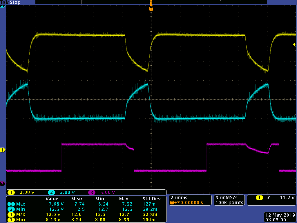
    Yellow and cyan in this case are my +/- 12 V supplies, and magenta is the output of my instrumentation amplifier. Any idea why this might be happening?

    Also, regarding your previous comments:

    1. What isolation resistor value do you suggest? Is there any literature that might help me out with that design point?
    2. Looks like the dips are not because of the sample and hold scheme.
    3. I did not know that there were dedicated sample and hold circuits -- I'll look into these since it seems to be far more elegant than the solution I have at the moment.

    Again, thanks for all of the insight. It has helped me a lot through the debugging process.

    -- Michael

  • Hi Michael,

    either the +/-12V switcher is damaged or the 24V input voltage isn't stable. Or is the circuit drawing too much output current from this switcher?

    An isolation resistor of 47...100R should help. See also these TI's stability training videos.

    Kai
  • Hi Michael,

    Kai's analysis is correct. In regards the the stability concern, you may view our TI Precision Labs series on stability here: training.ti.com/ti-precision-labs-op-amps-stability-1

    The videos cover several methods of compensation.

    -Tamara