This thread has been locked.

If you have a related question, please click the "Ask a related question" button in the top right corner. The newly created question will be automatically linked to this question.

THS6301: <Request> THS6301 AE measurement data and suggest

Part Number: THS6301

Hi,

Could you please help as below question:

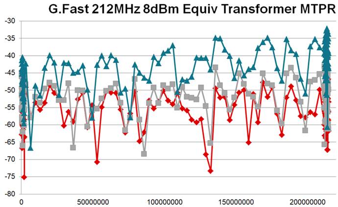
1.Need THS6301 actual measurement MTPR report as below:

2. Need THS6301 actual measurement Noise report as below:

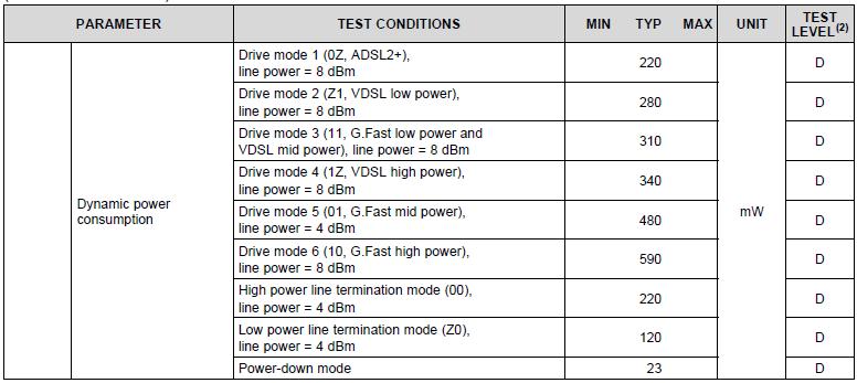
3.For dynamic power consumption, we choose Drive mode4(VDSL high power) and Drive mode6(G.Fast high power)

But do no try low/mid power consumption, have any suggestion? Which is good benefice?

4.For customer new project plan, master have VDSL(Long transmission/200Mbyte) /G.fast(Short transmission/2Gbyte) mode and slave line drive(THS6301)

Have any driver mode can support VDSL and G.fast at the same time? Or keep THS6301 G.fast mode support master VDSL/G.fast mode in the same time.

Warm Regards,

Lin 

  • Hi Lin, 

    Figures 16 through 24 of the datasheet show the measured results for the different MTPR values. 

    The modes essentially just change the power of the device. High power will give better MTPR and more bandwidth. You can adjust the power accordingly to find the best mode for your transmission. 

    It is very challenging to have a device that will support the full legacy VDSL requirements and the G.Fast requirements because the high output power required to reach full VDSL transmission power needs very large transistors that are then not fast enough for G.Fast speeds. This is why the THS6301 only supports 8dBm of VDSL output power. 

    Regards, 

  • Hi Jacob,

    Thanks for your reply.

    One more question confirmation:

    1.Have the THS6301 actual measurement Noise report?

    2. The THS6301 only supports 8dBm of VDSL output power? It will let our customer concern, because our VDSL output power will reach 14.5dBm.


    Warm Regards,

    Lin

  • Hi Lin, 

    The measurements in the datasheet are the actual measurements of the device. I'm not sure I understand your first question? 

    Our device can not support 14.5 dBm output power, that is correct. 

    Regards, 

  • Thanks Jacob,

    After confirm with customer, they need actual measure curve for noise floor (mode 00 & Z0) as same as the MTPR(figure 16~24).

    Did we have any data about that?

    Our device can not support 14.5 dBm output power, that is correct. 

    • Confirm datasheet test condition: VS=12V, Av=8.5V/V, PAR=15
    • G.FAST 212MHz 8dBm(mode 10) with transformer(1:1.5)
    • G.FAST 212MHz 4dBm(mode 10) with transformer(1:1)
    • VDSL 35B 8dBm(mode 1Z) with transformer(1:1)

    On VDSL 35B this case, can’t we use transformer(1:2) to reach 14.5dBm?

    Or even change transformer turn ratio just support to 8dBm for VDSL?


    Warm Regards,

    Lin 

  • Hi Lin, 

    To estimate the noise floor the customer can just look at the input referred voltage noise and use the correct noise value for the bias setting and then multiply by their gain to the output. 

    The MTPR curves were all measured with Av = 8.5 and a 1:1 transformer. It may be possible to use a 1:2 transformer to reach 14.5 dBm but a larger transformer ratio puts a higher output current demand on the device. It can certainly swing the correct voltage, but I would expect some performance loss in the MTPR measurement. 

    Regards, 

  • Hi Jacob,

    To estimate the noise floor the customer can just look at the input referred voltage noise and use the correct noise value for the bias setting and then multiply by their gain to the output. 

    =>  I know how to estimate/calculate the noise floor, but we want to check the actual measure report.

    The MTPR curves were all measured with Av = 8.5 and a 1:1 transformer. It may be possible to use a 1:2 transformer to reach 14.5 dBm but a larger transformer ratio puts a higher output current demand on the device. It can certainly swing the correct voltage, but I would expect some performance loss in the MTPR measurement. 


    =>  If all the case test condition with transformer ratio 1:1 including G.fast/VDSL, but the page 21 of datasheet have mention use 1:1.5 for G.fast 8dBm.

    What’s the different? Because I check the 1:1 measure curve is the same as 1:1.5(G.fast 4dBm & 8dBm).

    => If we want to use 1:2 for VDSL 14.5dBm, is means the higher output current will dominate the performance? Have measure curve(MTPR) can reference?

     =>How about the THS6301 headroom value?

     Warm Regards,

    Lin

  • Hi Lin, 

    I am double checking on what transformer we used for those measurements. I see the confusion between the electrical characteristics and the information on page 25. 

    I will also look to see if we have noise floor data, but I'm not sure if we measured it without any signal present. I will also see if we have performance measured with a 1:2 ratio. 

    The THS6301 can swing a minimum of 18Vpp at the differential output on 12V supplies. This means 9Vpp on each output and therefore 1.5V of headroom is required to each supply for the individual outputs. 

    Regards, 

  • Hi Lin, 

    I have verified that we did use s 1:1 transformer for all MTPR measurements listed in the characterization data. We did also measure the part at 212MHz G.Fast with a 1:1.5 ratio transformer. At 8dBm power, the 1:1.5 transformer had an average 212MHz MTPR of -52.14dB versus the 1:1 transformer average of -55.43 dB. Unfortunately I only have the noise floor data for the power down and receive modes. 

    Regards, 

  • Hi Jacob,

    Thanks for your information.

    Can we get the MTPR measurement curve with 1:1.5 ratio transformer at 8dBm power?

    As like the datasheet display as attached file.

    We can review the noise floor for power down and receive mode first, please show the measurement curve.

    Thank you .

    Warm Regards,

    Lin 

  • Hi Lin, 

    Here is the 212MHz MTPR performance using different transformers, the lower power receive mode noise floor, and the power down noise floor plots in that order. 

    Regards, 

  • Hi Jacob,

    (1)   From the datasheet, it often declare PAR=15dB, if TI defines PAR =- 10 log (Vp/Vrms)2)?

    On page21 of datasheet attached “G.Fast, 106-MHz, 212-MHz transmit profile Yes, using the bias control pins for line power = 8 dBm and PAR = 15 dBm”

    Is this a typo of dB?

    (2)   Also, on page 21, it claims it’s @ transformer turn ratio 1:1.5, and from the description 8.2.2,

    Does it means we should put a RT=100ohm/5 / (1.5)2 = 8.9ohm on secondary side center-tapped? And use Rseries = (100ohm/1.52) /2= 22.2 ohm on Figure42?

    Besides, shall we still finetune the primary side capacitor 2200pF?

    (3)   According to the table2, Transformer primary side V =0.794Vrms = 4.465 Vp @PAPR=15, so , the THS6301 O/P Imax will be (4.465Vp/1.5) /(44.5+8.9)ohm = 55.7mA, and the O/P swing Vmax will be 55.7mA x (44.5x2 + 8.9) = 5.45Vp-p?

    Can you provide us the suitable transformer model spec. TI used?

    (4)   As I explained you, we plan to apply THS6301 to work at 1:1 for dual-mode 8dBm G.fast (212MHz) and 8dBm (about) VD35b,

    Have you any practical 3-order low-pass filter (L1, L2, C1, C2) recommend value?

    And what bias mode will you suggest? G.fast: TRx, V35b: Tx, Rx

  • By the way,

    Can we get MBD(Missing Band Depth) test report?

    We want to check MBD performance at 10M/100M/200MHz.

    You can refer below picture that measure high frequency(200MHz) of MBD.

  • By the way,

    Can we get MBD(Missing Band Depth) test report?

    We want to check MBD performance at 10M/100M/200MHz.

    You can refer below picture that measure high frequency(200MHz) of MBD.

  • Hi Jacob,

    Any update?

    Our customer are urgently need to get these answer for next step design-in.

    Warm Regards,

    Lin 

  • Hi Lin, 

    Unfortunately I don't have a missing band depth test report for this device. If you are using a 1:1 ratio transformer then I suggest you stick to the 47.5 ohm series output resistors as used for the characterization of the device with the 1:1 transformer. We de-embedded the transformer for most of the measurements made in the datasheet. To model the transformer behavior, you will have to refer to the manufacturer of the transformer you are using. 

    The PAR for your first question is just a typo, and you shouldn't need to tune the primary side capacitance if you aren't changing anything significant. I would suggest filtering on the receiving side of the signal chain instead of the line driver side so you aren't adding even further parasitic elements to the output circuit. 

    I would also suggest trying out the EVM for the device. It will allow you to run a lot of the experiments we have been discussing and assess the device performance for your particular application. 

    Regards, 

  • Hi Jacob,

    What’s gap between datasheet and our measure(yellow circle)?

  • Hi Jacob,

    What’s gap between datasheet and our measure(yellow circle)?

  • Hi Lin, 

    Can you tell me the conditions you were using for the test? Was this with a 15dB PAR and a 1 in 64 missing tone profile? Which bias mode was the device in? 

    The various "spikes" that you see in the wave forms are going to vary somewhat between different device setups. Often these peaks and valleys are effected by the parasitic elements on the board and test equipment so each environment will change the shape of the waveform. 

    Regards, 

  • Thank you Jacob.

    By the way, 

    Please refer attach file.condition.

    Can you help to measure MBD(Missing Band Depth) on your side?

    We want to check THS6301 MBD performance for turn ratio 1:1 or 1:1.5 @212MHz/8dBm

    Thanks! 

    THS6301 G.Fast MBD Mesurement Report.pptx

  • Hi Lin, 

    Unfortunately we don't have the infrastructure set up to measure missing band depth, but it should be similar to the device MTPR performance if you compute the absolute value of the missing tone. 

    Regards,