This thread has been locked.

If you have a related question, please click the "Ask a related question" button in the top right corner. The newly created question will be automatically linked to this question.

INA128: Differential filter

Part Number: INA128
Other Parts Discussed in Thread: INA821, ADS1299

Hi Folks,

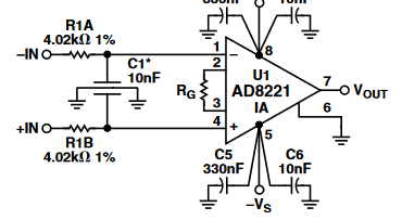
on the image below there is an X2Y example configuration to increase high CMRR:

but in my application I need 8 input channels with one common signal, so I have to connect the IN- signals together forming one COM signal.

The question is, that can I use this X2Y configuration above, or should I place distinct RC low pass filters into the IN(x) signal path and into the COM too and add an X cap between the COM - IN(x)?

My observation is that I place 8 times such a X2Y cap, the COM signal will have an RC filter with C = SUM(C(number_of_channels)) towards to GND.

Does this mean any problem, or can I do it by this way, any suggestion?

Regards,

Norbert

  • Hello Norbert,

    The C1 in the above instrumentation amplifier application is an X2Y® capacitive circuit. When applied with the R1A and R1B resistors it creates both common-mode and differential-mode filters! Additionally, the capacitor structure results in very close tolerance of the two, common-mode "Y" capacitors which benefits the common-mode balance of the filter.

    If you were to connect the inverting inputs of 8 of the instrumentation amplifiers together to just one R1A, C1 circuit that would load the filter unevenly with respect to the non-inverting side. That would imbalance the filter circuit and the common-mode performance would be degraded. Maintaining common-mode performance is often more important than the differential performance because unwanted noise and interference most often enters the circuit as a common-mode signal. Unbalancing the common-mode circuit common-mode noise/interference accommodates common-mode to differential signal conversion where the latter is readily amplified by the instrumentation amplifier.I would use separate resistor, plus X2Y® capacitive circuits for each instrumentation amplifier to maximize balance.

    By the way, if you might have interest in TI's equivalent instrumentation amplifier for the one you show in your circuit please see the INA821. You can find its information here:

    http://www.ti.com/product/INA821

    Regards, Thomas

    Precision Amplifiers Applications Engineering

  • Hi Thomas,

    yes, I prefer TI products, the image was only for demonstrate my problem. My real project is an AD converter (ADS1299) but I won't to post my question into the data-converter forum, because I think, my interest is more close to this forum.

    So: ADS1299 allows to connect all inverting inputs together and use it as one common reference (COM). This setup is an expectation from my customer, even trough by this way we can save 7 cables compared to the fully differential wiring.

    I know the very closely balacned nature of the X2Y capacitors and it is because I wanted to see whether is it possible to use it or not.

    My concern (let us use 8 channels with one COM signal) was if I use 9 distinct capacitor, the CMRR will be decreased by the cap tolerance, that can about 2 times 20% per channel (as I have to place 1 RC filter into the COM signal and an another into the particular channel), but using the X2Y cap I can get much better CMRR due to the two balanced Y capacitor.

    Can I balance "back" my COM signal path by using an 8 times less resistor (theoretically the cut-off frequency should be the same...)

    Regards

    Norbert

  • Hi Norbert,

    Tying the inverting inputs of 8 INA821 instrumentation amplifiers together along with their 8 individual X2Y® circuits would result in 8x the C1 value. Since there would be 8x the C1 capacitance at this common connection, then it would be necessary to reduce the R1A resistance in that circuit by 8x. That way both sides of the X2Y® circuit would maintain the same cutoff frequencies. The INA821 input is an extremely high input resistance, low capacitance, even 8 tied together will have little effect on the R1, C1 frequency response. Some optimization of R1A might be required to maximize the common-mode performance.

    Regards, Thomas

    Precision Amplifiers Applications Engineering