This thread has been locked.

If you have a related question, please click the "Ask a related question" button in the top right corner. The newly created question will be automatically linked to this question.

Need a suitable Class D amplifer for high voltage and current application

Other Parts Discussed in Thread: OPA551

My intention is to make an 3-phase power calibrator !

Similar to this link, https://us.flukecal.com/products/ele...wer-calibrator

My current design might be class AB type. 


I am not worried to much about PWM generation ruther I am thinking how can I move class AB to Class D amplification.


A lot of the design effort relates to maintaining linearity and avoiding crossover distortion.


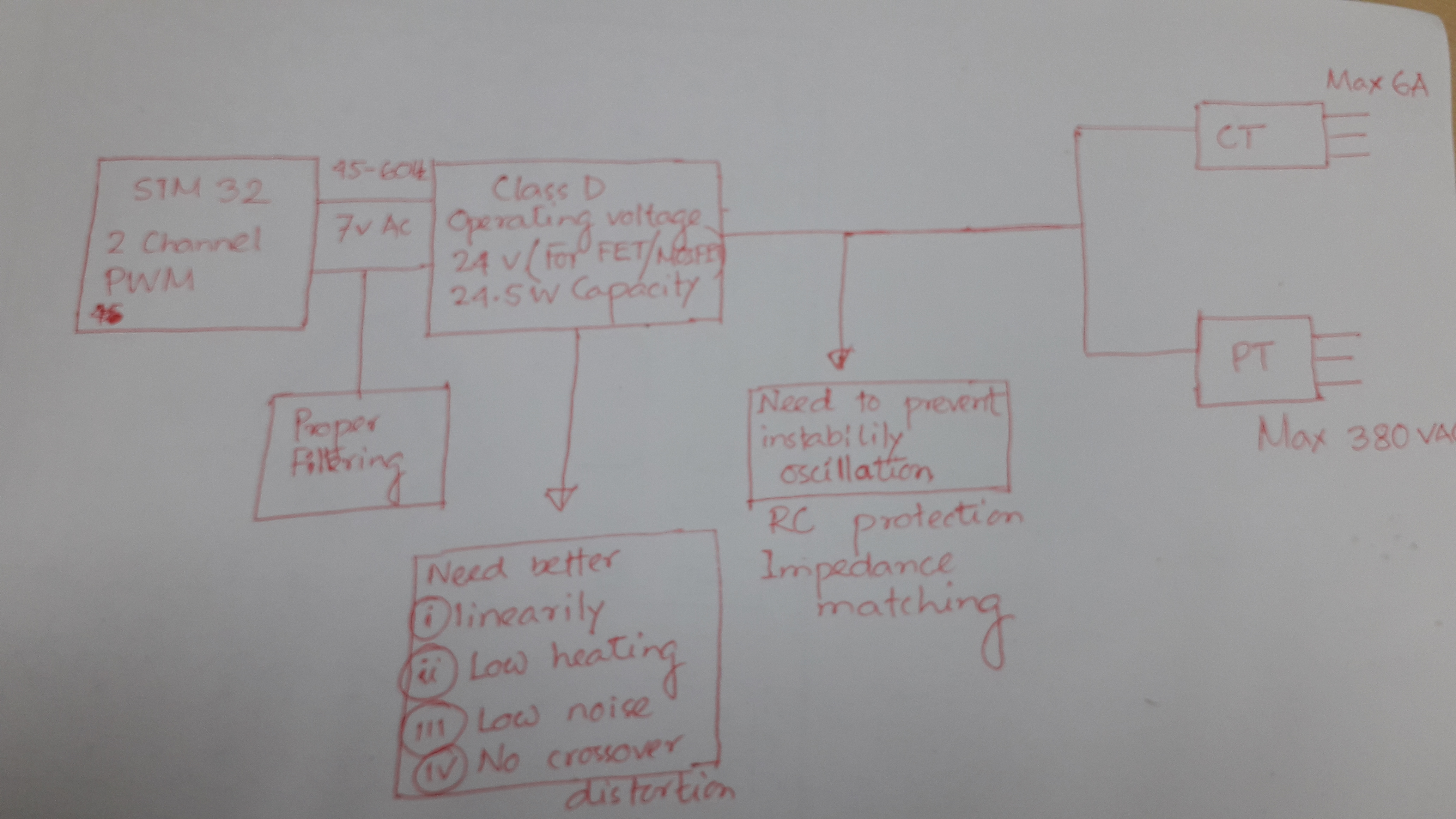
2  amplifiers( current, voltage)  output will feed to CT and PT! Lets consider load will be connected in their output!


REQUIRMENTS :


1. The amp input  should be  plus and minus 7volt AC, 45-65Hz( 1 Hz has been converted to 1024)

2. Amp operating voltage should be more or less 24v.


3. 2 channel signal (not sure PWM) should be use , one for current, one for voltage.


4.Can run current transformer(input 16.5 V/1.5 A)  and potential Transformer (input15v/2A). PT output may be 15VAC.

5. If possible both voltage and current amplification is required in one IC.

6. Both positive and negative half signal should be amplify. ( take a look bellow 


For CT, current transformer primary winding has 80turns, 16.5 V/1.5 A, secondary has 20Turns, 4.125v/6A output!
For PT, Potential transformer, Primary has 80turns, 15v/2A rating input, secondary has centertap!
At secondary 960turns, 360v/0.332 A and 960turns 180v/0.166A output.

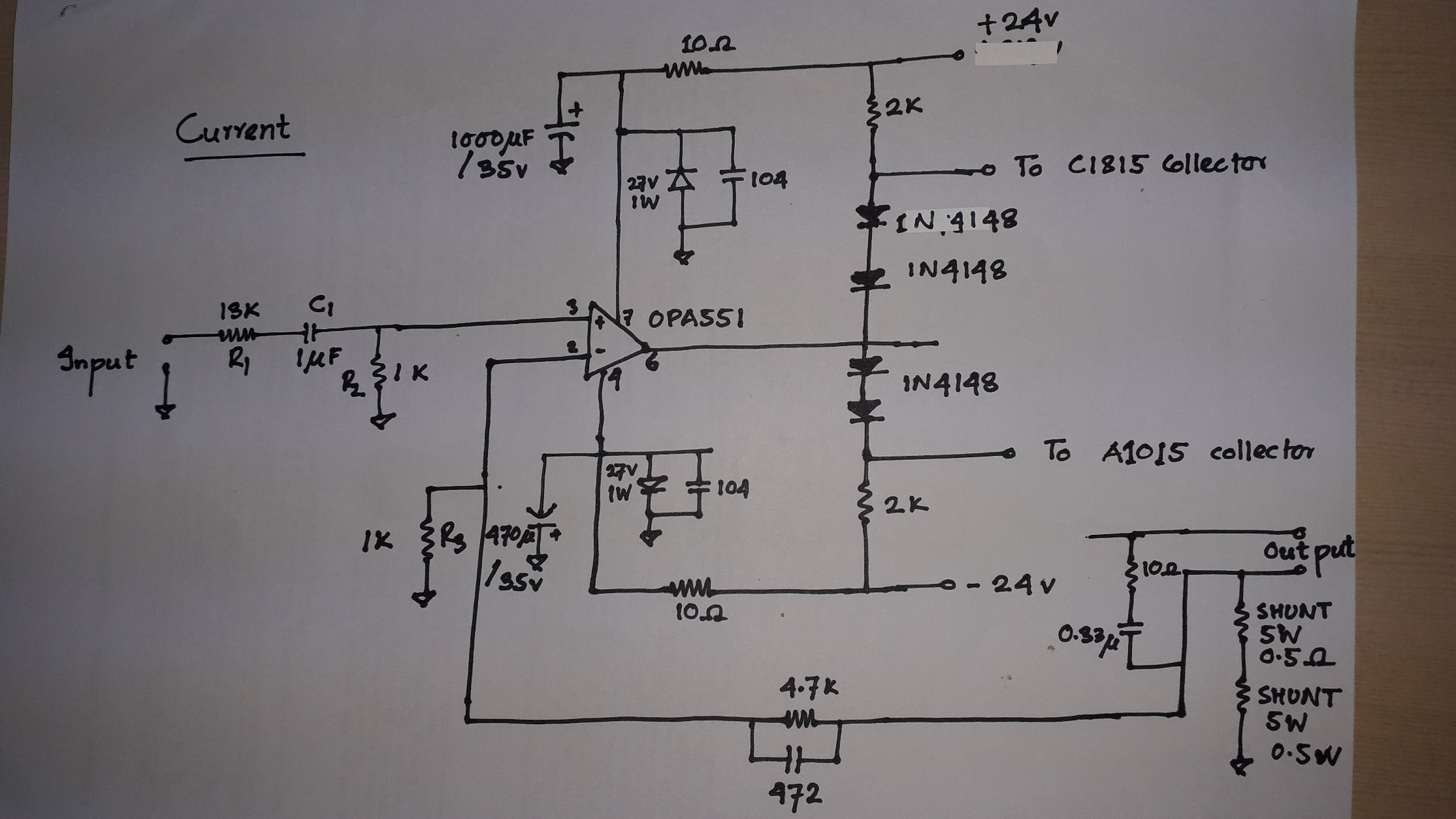
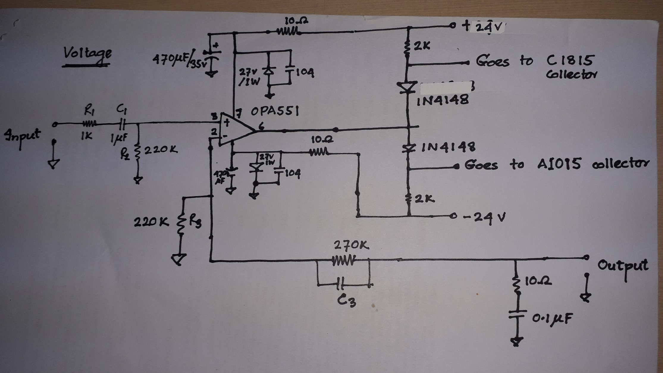
I am using TIP147, TIP142, C1815, A1015. They are properly biasd like cascaded 3 stage, may be AB class network. More symmetric way, like one pairs AB class output is connected to others pair. Last pairs base is connected to first pairs base! At last a voltage divider of 5 ohm has been made between 2nd and 3rd outputs!


Now lets come to the point, I am talking about the feedback amplifier

  • Hello Hasan,

    If you decide to go the class-D route TI has a wide catalog of class-D and boosted class-D amplifiers intended for high-power audio applications. Certainly the 45 to 65 Hz used in your calibrator application would fall within the audio frequency range. Here is the URL for the TI power audio products:

    http://www.ti.com/audio-ic/amplifiers/speaker-amplifiers/overview.html

    The class-D amplifiers are supported on another TI e2e forum, which I believe is the Audio forum. Any questions about those products should be directed to that forum for the most complete support.

    The OPA551 shown in your two schematics are supported on this Precision Amplifiers forum. The current and voltage amplifier circuits look like you have put a lot of thought into them, but because there isn't information about what is applied at the "Output" points, or what the A1015 collector and C1815 collector indicate I can't fully assess the circuits. Do the transformers connect at the anode/cathode common-point of the 1N4148 diodes? Do note that 1N4148 diodes are small-signal diodes and not suitable for back EMF protection of the OPA551. Ultrafast rectifier diodes are required for that task.

    Regards, Thomas

    Precision Amplifiers Applications Engineering

  • Hello  Sir Thomas,

    Thank you very much to join in this discussion.

    The feedback amplifier I posted is for "ClassAB" type. Its a current feedback amplifier indeed. Current and voltage feedback amplifier has little difference in this case.

    Looking at the inputs of C1815 and A1050 , these are common emiter pair input helping to biasing or driving TIP142 and TIP147. In this case AB class is  having " Darlington" or " voltage boosting mode"

    I am looking for such high current desity in ClassD.

    Now another challenge is maintaining transformar input from ClassD applifier output.

    People also curious about" core saturation" effect.

    "A product with a Class-D audio power amplifier (APA) driving an output transformer with inadequate           low-frequency performance may shut down when its output is stepped from zero to maximum at the start   of a sine cycle. Shutdown is triggered by short circuit protection (SCP), after the first half cycle of the sine output. The root cause is saturation of the transformer core."

    Kindly suggest me also reference design. If possible transfer this thread to " Audio amplifier " group.

  • Hi Hasan,

    As we get connected in an other thread, let's close this one.

    Regards,

    Hao