This thread has been locked.

If you have a related question, please click the "Ask a related question" button in the top right corner. The newly created question will be automatically linked to this question.

INA240: Bucket Filter Calculation and Verification

Part Number: INA240
Other Parts Discussed in Thread: TIDA-01629,

Hi,

I am using a INA240A1 in a similar configuration as the in the TIDA-01629 Reference Design: http://www.ti.com/tool/TIDA-01629
Unfortunately I see some coupling between channels sampled sequentially.

It looks like this is caused because I am using the wrong values for my RC Bucket filter between my INA240 and ADC.

In the next  post: https://e2e.ti.com/support/amplifiers/f/14/p/848996/3141486#3141486
TI gives already a lot of information, but I am still not completely sure how to calculate it correctly.

I filled in the specs of my MCUs ADC (STM32F3) in the Analog Engineer's Calculator:

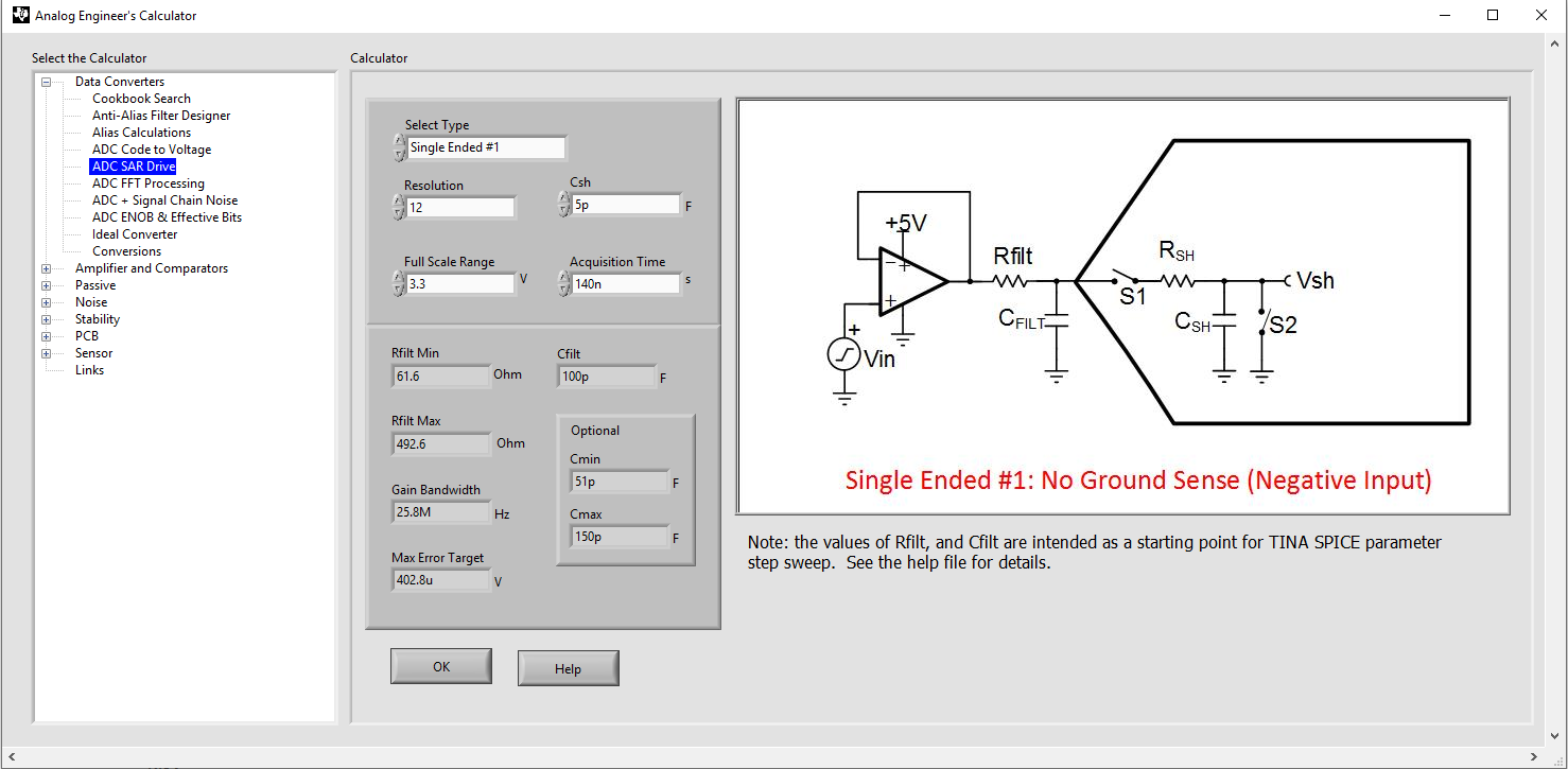
How do I calculate the Gain Bandwidth of the INA240A1? Is this 20*400kHz = 8MHz? So do I need to increase my sampling time to >450nS
How should I handle the Zout of the INA240 plotted in the previous topic? 
How do I verify that the INA240A1 is stable with the calculated values.

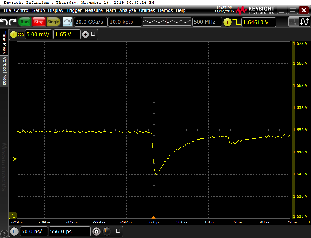
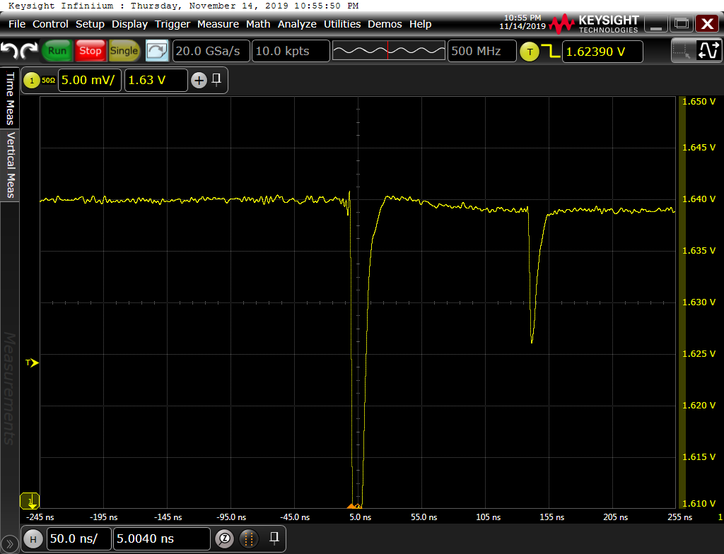
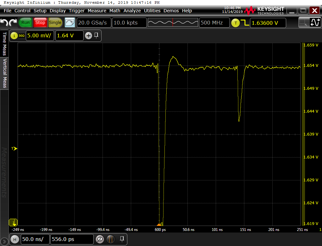
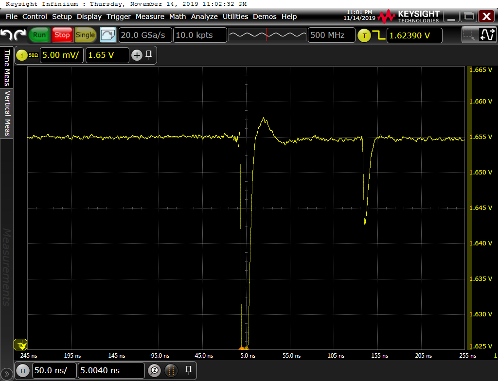
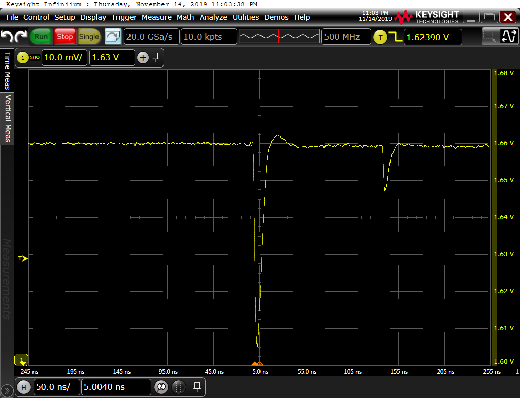
Is it also a good approach to measure with a Keysight N7020A Probe over the Capacitor (100pF) and adjust the resistance values till I have a critical damped response when the Sampling Capacitor is switched on?

  • Hi,

    The bandwidth of INA240A1 is about 400KHz, gain bandwidth doesn’t apply to a closed loop system such as this device.

    INA240A1 is able to drive the 100pF cap directly. You shouldn’t have stability problem, but of course you should check with a probe. You likely don’t need the isolation resistor, but is OK to have. Further you should be able to drive the ADC directly as the TIDA has done.

    Is the 450nS the blanking time? If so, it is too small, it should be at least a few uS. You want to time the sampling so that it is sufficiently away from any switching event, even if it is on another phase.

    Regards, Guang

  • Thank you for your answer.

    This 140nS/450nS was about the sampling time.
    The Sample frequency of this channel is 20KHz, synchronously with the PWM frequency, and in the middle of the low side MOSFET on cycle.

    I made some measurement on the Cfilt for some different values with a sampling time of 140nS

    Rfilt: 470R, Cfilt: 1nF

    Rfilt: 100R, Cfilt: 1nF

    Rfilt: 22R, Cfilt: 1nF

    Rfilt: 470R, Cfilt: 100pF

    Rfilt: 100R, Cfilt: 100pF

    Rfilt: 22R, Cfilt: 100pF

    Rfilt: 0R, Cfilt: 100pF

    Rfilt: 100R, Cfilt: 0pF, 10mV/div to also see the bottom of the valley.

    The amplitude of the step response is depending on the (rest) charge of the sampling capacitor from previous channel.

    For me it looks like that the Cfilt of 1nF is too big to get settled with this sampling time.
    I am wondering how that works out for the TIDA-01629? Is that only working because of the smaller sampling capacitor of 1.6pF of the TMS320?

    Or would it be even better if I would use a much bigger Cfilt capacitor (22nF?) to able to get all charge from the Cfilt capacitor?

  • Hi,

    The smaller sampling capacitor definitely helps.

    Obviously with a larger filter cap, the delay has to be bigger. A 1nF+100Ohm should be good enough. The delay needs to be close to 1uS for the signal to settle to within 1/2LSB of the ADC.  

    You probably don’t want to make the cap too large either, otherwise it may limit the system bandwidth. I would stay below 22nF.

    Regards, Guang