This thread has been locked.

If you have a related question, please click the "Ask a related question" button in the top right corner. The newly created question will be automatically linked to this question.

THS4631: About the analog integrator based on op amp

Part Number: THS4631
Other Parts Discussed in Thread: ACF2101

Hi TI expert,

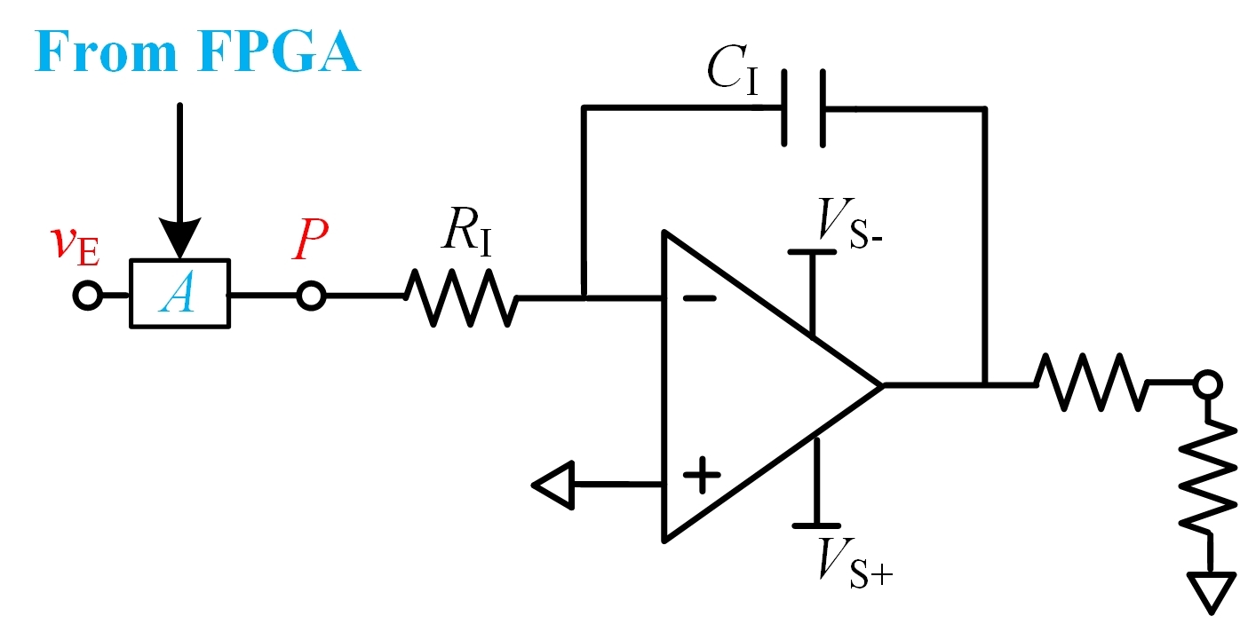
My problem is as the figure below.

Based on my application, I need to find a subcircuit or component, denoted as A. A can be controlled by FPGA/CPLD. When FPGA makes A conduct, input voltage vE is integrated. When FPGA makes A turn off, vE is then blocked from the integrator.

When on, A's resistance should be much smaller than integration resistance.

vE is at most between +-30V. And I've been thinking about using MOSFET as A.  However, voltage at P is changing when integrator works and I then need to use iosltaed power for the MOS and isolated buffer so that FPGA can drive the MOS.

I consult you experts for a simpler and better solution,

Regards

Yatao

  • Hello Yatao,

    To confirm your signal ranges between -30V and 30V? Also what is the frequency range of your input?

    Best,

    Hasan Babiker

  • Hi Hasan,

    Thx for reply.

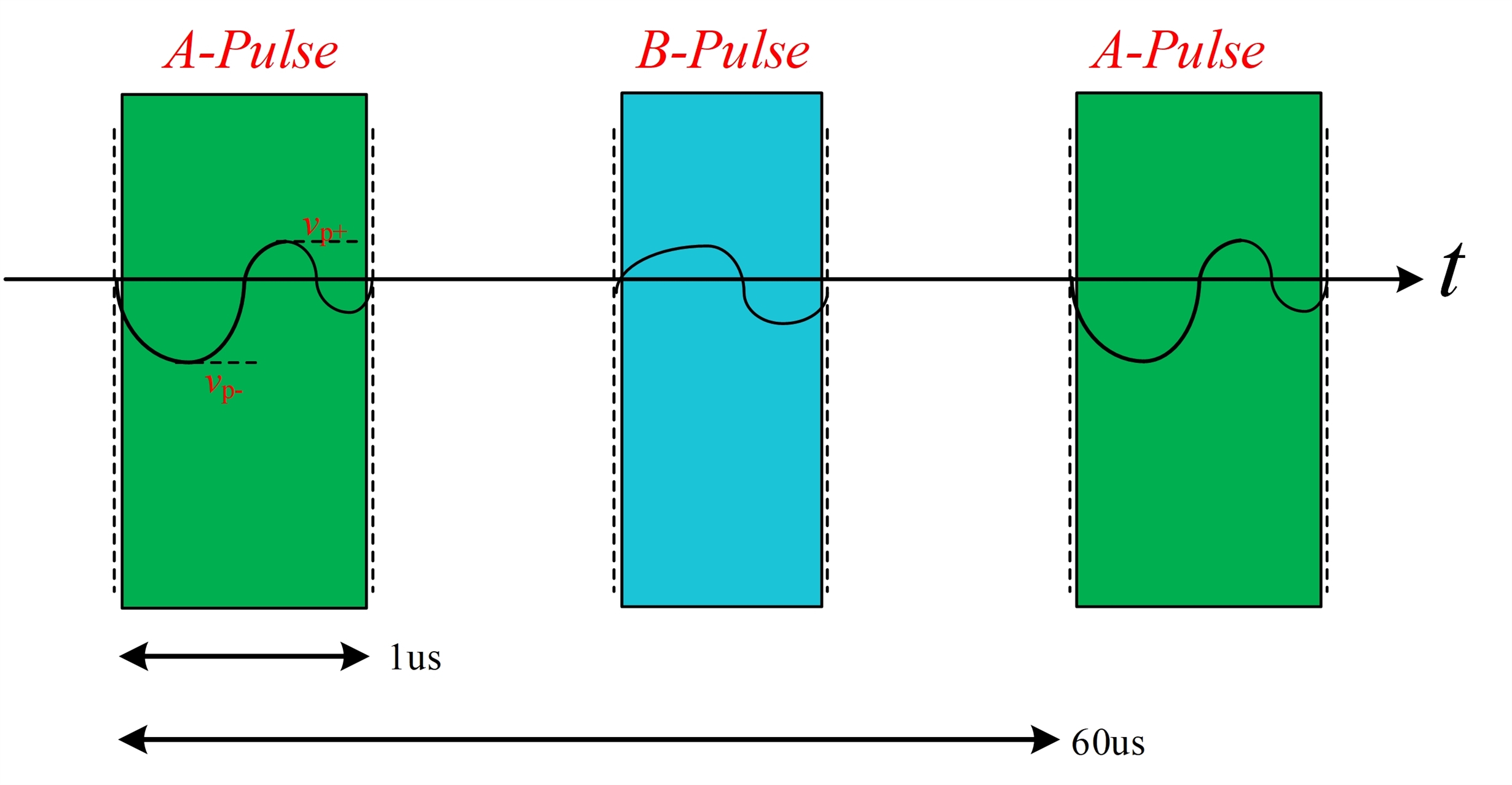
    The input signal vE is periodic as the figure below. A-pulse and B-pulse occurs at vE in turn. The shapes of A- and B-pulse are approximations.

    A-pulse should be fed to the integrator and B-pulse should be isolated by subcircuit A from the integrator.

    As can be seen from the figure, the period is 60us and A-pulse lasts for more than 1us.

    vp+ in the figure is no larger than 30V and vp- is no lower than -30V. Peak values for B-pulse are also within -30V and +30V.

    Regards

    Yatao

  • Hi Yatao,

    unfortunately we don't have a device that covers this voltage range. I couldn't find a simpler solution than using MOSFETs

    Best regards,

    Ambroise

  • Hi Ambroise,

    Thx!

  • Dear Yatao,

    how are you?

    I think a simple MOSFET will not properly do the job because of charge injection. What you need is a special HF signal analog switch offering an ultra low charge injection.

    By the way, why are you doing all these signal manipluations with such a high supply voltage. I see no need to do all this with a supply voltage of +/-30V. I would run all these circuits with a much lower supply voltage and amplify the manipulated signals afterwards in suited output buffers. Have you thought about this?

    Kai

  • Hi Kai,

    Nice to meet u again. Thx for your attention.

    It should be early in the morning in the US. You get up so early and are so hardworking.

    Actually, input signal vE is the induced voltage across parasitic inductance in power semiconductors and its magnitude is decided by the load current flowing.

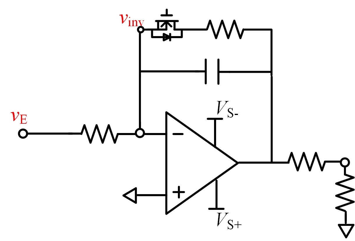
    I've come up with a simpler solution myself as the figure below.

    I move the subcircuit away and introduce reset MOS for the integration capacitor. A short time ahead of A-pulse, I'll turn off the mos and the integrator works. Short time after B-pulse, I'll turn on the mos and the integrator output will be reset. If the output is positive, output be discharged by MOS channel. If negative, the discharding will be via body diode in the MOS. Since I only care about the integration output after A-pulse starts and before B-pulse begins, the reset before A-pulse can avoid wrong accumulation from cycle to cycle.

    I paln to use TI's http://www.ti.com/cn/lit/ds/symlink/ucc20225a-q1.pdf to drive the small MOS and provide isolated power for the chip and MOS, with vinv as the ground level.

    Regards 

    Yatao

  • Hello Yatao,

    Here is my suggestion: convert the voltage into current at Ve; using current mirror circuit to duplicate the input current at point P, then integrate the duplicated current. This may create isolation from Ve. 

    Take a look at ACF2101 integrator, it may be able to handle your application. 

    Best,

    Raymond

  • Dear Raymond,

    Thx for your advice.

    I'll take a look at the chip.

    Besides, the solution I propose can also work, I think ^ ^

    Regards

    Yatao