This thread has been locked.

If you have a related question, please click the "Ask a related question" button in the top right corner. The newly created question will be automatically linked to this question.

OPA188: OPA188 SPICE model

Part Number: OPA188
Other Parts Discussed in Thread: LM10, OPA454

Hey there

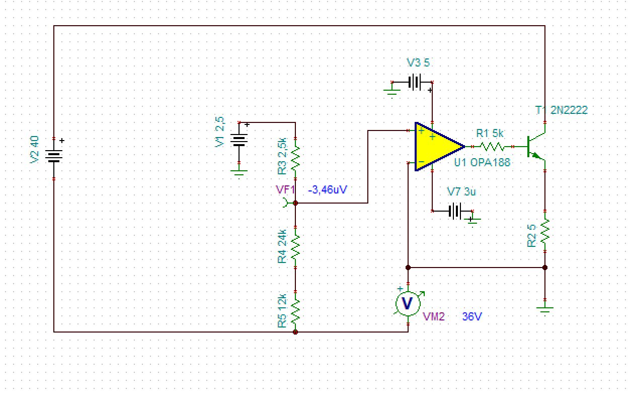
I need to run a circuit simulation involving OPA188 but I cant find a compatible SPICE model. I'm using EasyEDA which uses standard SPICE2 and SPICE 3 models but  the only thing i've got so far is a TI TINA model. 

Can anyone provide the correct spice model or a recipe to convert form TINA to SPICE?

Regards

  • Hey Angelo, 

    If you go under the design and development tab on the product folder, there is usually a spice option - this zip will show a .lib option which what you want I think, I meant to circle the top row here. 

  • Hi Angelo,

    Michael is correct. All our models are un-encrypted. You may find the .lib file and import it into your simulator. 

    OPA188.LIB

    -Tamara

  • Hi Michel and  

    Thank you for your answer but my problem is still unsolved due t other EasyEDA issues. So I decided to go for TINA simulation and didn't have better luck.

    I reduced the circuit to a minimum concept and simulated in TINA. As you can see in the image below, it works when using an "ideal" OpAmp mas doesn't work when using the real OPA188 Tina model.

    What should be the right simulation parameters top make the model work in this simple circuit?  Below is the TINA schematic in case you want to take a look at the parameters (all default).OPA188_test.TSC

    Thanks again

  • I think you have the feedback in the wrong place, essentially forcing  a large delta V across the inputs pegging the amp to the rail, 

    If I fix that, the next issue is your 5k base R is causing too much IR drop again pushing the output to the rail, 

    If I reduce that R to 200ohms we now see equality for the two op amp inputs meaning it is running closed loop now, but just barely - op amp output pin is off the rail but not by much - must still have a lot of base current to support that 468mAin the 5ohm load

    I am not sure that transistor can handle that much, but anyway the sim is working now I think, 

    updated ckt. 

    OPA188_current source.TSC

  • Hi Angelo,

    as already mentioned by Michael, there are two important drawing mistakes in your schematic, the missing ground at V2 and the missing feedback path from R5 to the -input of OPA188 in your current source. Besides the improperly assumed current gain of 2N2222 there is another issue with this transistor: It's impossible for the 2N2222 to dissipate the power! The collector current of 2N2222 is 2.338V / 5R = 467.6mA. The collector emitter voltage is 40V - 2.338V = 37.66V. This results in a heat dissipation of 2N2222 of 37.66V x 467.6mA = 17.6W. This is way beyond what can be dissipated by the 2N2222!

    You might ask yourself why the voltage at the input voltage divider can break down? Well, according to figure 43 of datasheet of OPA188 there are diode clamps between the inputs. So, a too low potential at the -input of OPA188 will also pull-down the +input of OPA188.

    Kai

  • Hi Michael and Kai

    Thank you so much for your support.

    Unfortunately  I don't think that  the feedback is the problem because R2 is too small (5 Ohms) and it is there just for current sensing purposes to be added later. As I said before I reduced the schematic to a minimum just to inspect the opamp issue . Anyways it works with the ideal opamp. 

    I'm afraid your suggestion didn't work either because what i'm trying to acvhieve is a floating 36 Volts power supply like this exemple taken from a TI AppNote ():

    The only differences are:

    1) LM10 has internal voltage reference (in my case replaced by V1= 2.5V)

    2) The transistor output stage gain which is not required because the system will provide less than 150 mA of output current

    3) The opamp is getting supply current from Vin which is not necessary in my case because I have 5V available in my board (represebted by V3)

    As you see, the real negative feedback in this circuit is provided through "+" input of the opamp (because the  transistor provides inversion).

    This "float" configuration does require a rail-to-rail opamp with low offset drift and this is the reason I've chosen OPA188.

    I still believe there is something inadequate with simulation parameters but unfortunately  I'm not a good enough SPICE user.

    Please let me know if I'm wrong.

    Regards

    Angelo

  • Kai

    Thank you for you answer. Please read my response to Michael below.

    Regards

  • Hi Angelo,

    I'm afraid, but I do not understand what you say :-)

    Can you please describe in very detail what you want to build?

    Kai

  • Hi Kai,

    I want to build a floating 36V power supply using OPA188, almost identical to this:

    Thanks,

    Angelo

  • Hi Angelo,

    Where did you find this circuit (bootstrapped regulator)? I would like to look into this document more.

  • Hi Tamara,

    it's from an appnote which can be found on the product site of LM10:

    AN-211 New Op Amp Ideas

    Kai

  • Tamara,

    This is a classic configuration, but anyway, I've found this particular case in the following TI Application Note:

    http://www.ti.com/lit/an/snoa638a/snoa638a.pdf

    Anyways, my original issue remains and it is a matter of simulation parameters.

    Regards

  • Hey Angelo, 

    If you mean you still need a PSpice model file it there on the product folder. 

    I have LTSpice on my computer and if I chase that zip file down and double click the .lib file it opens in LTSpice to show the model net list. If that is not useful for you, you could take a known working op amp model in your simulator and paste over the lib file contents and res-save as a OPA188 model file perhaps 

    here where that file is, 

    Here is what it looks like opening the .lib file in LTSpice, 

  • I was also looking at the app ckt using the LM10 - you know that is really kind of a special part

    If you are just trying to delivery a higher voltage power supply, take a look at the OPA454 100V opamp along with this external transistor idea if you need more current. 

  • Michel, 

    Thank you again for the model. 

    Now,  the circuit topology is proven correct and I have the right model but  the simulation doesn't render the right result. Certainly it is because of the simulation parameters, the topic of my original question.

    Regards

    Angelo

  • This proofs my case: VEE >= -3 microvolts makjes the model work.

  • Thanks for the feedback, we will look into this model.