This thread has been locked.

If you have a related question, please click the "Ask a related question" button in the top right corner. The newly created question will be automatically linked to this question.

INA181: Overload response

Part Number: INA181
Other Parts Discussed in Thread: TLV7041, TLV7031

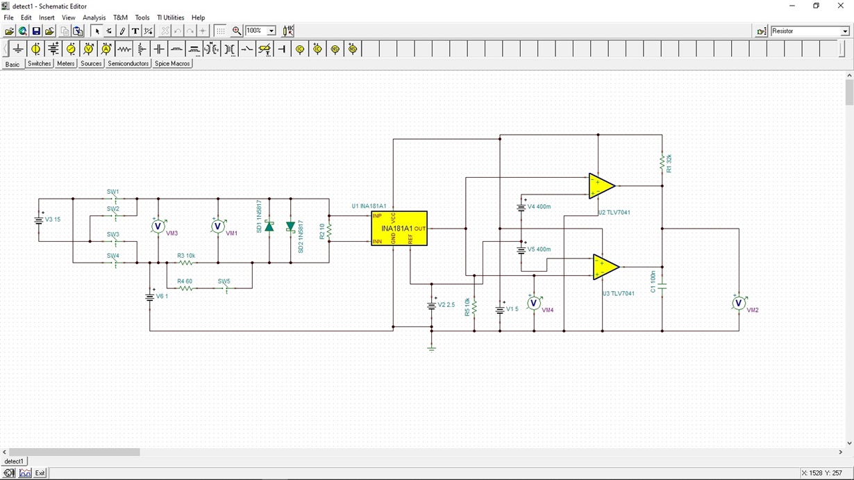
I am looking at using the INA4181A1 (quad INA181A1) as a threshold current detector. I want to know when current exceeds a min level (~ 2 to 5ma). The current could be as high as 5A. Using a 10ohm sense resistor with a pair of schottky diode clamps. The supply is a bipolar PW encoded data stream from an H bridge driver. The diff input clamps ~.4v so the INA181 is driven to both rails. This is not a problem since I am not actually making measurements.

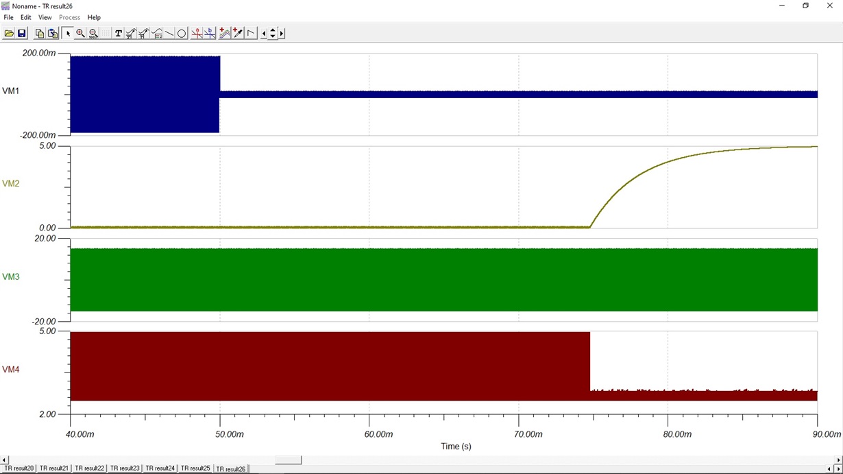
The spec sheet says output  should return to normal ~20us after overdrive is removed. I ran a TINA Sim and found its taking ~25ms for the output to recover. I tried with and without 10k loads on the output.

Attached are screen shots of the circuit and plots. Am I missing something or is my sim flawed?

Steve Green

  • Steven,

    Thank you for using the forum to look into your question.  First let me say that some models to not represent the devices well outside of its operating range as some of these response are very complex.  I do not believe this model does what you need to model but I will look into and let you know a business day or two. 

  • Thank you.

    Even if the response is this slow, It actually doesn't affect the operation that I want to achieve. I was just surprised to see how long it took.

    Steve

  • Hi Steve,

    can you post your simulation file?

    Kai

  • File attached.

    Sorry I didn't see the reply at first.

    Stevedetect1.TSC

  • Hi Steve,

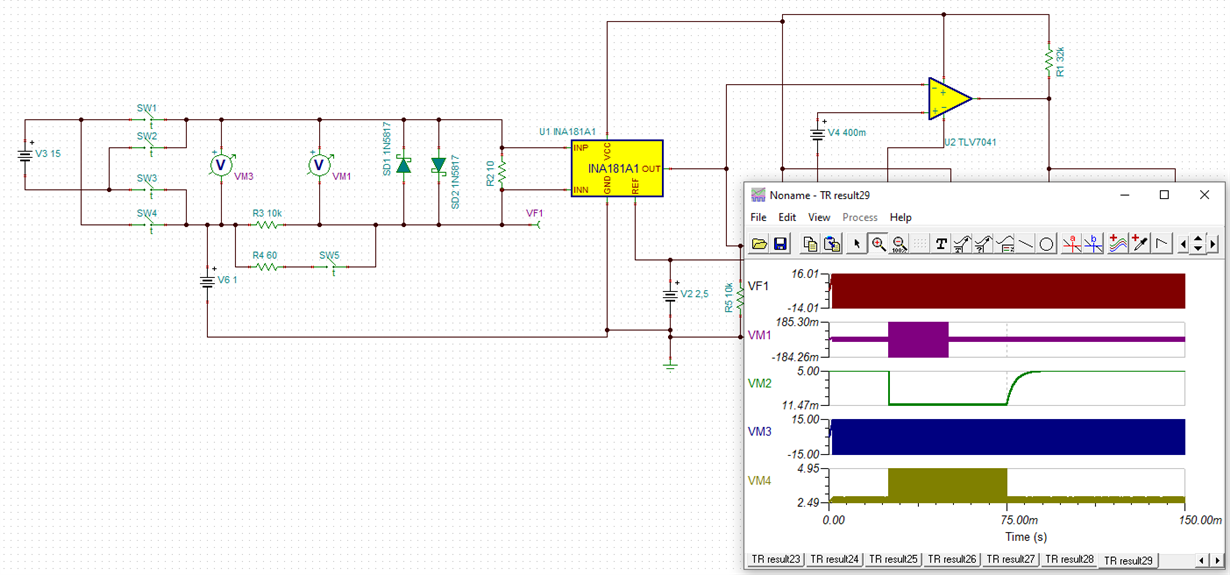
    you violate the common mode input voltage range of INA181. The input voltage should not go below -0.2V. But look at signal "VF1":

    There's still another issue but which has not to do with the overload response of INA181: Remove C1 at the output of comparator. The TLV7041 has a push-pull output stage. Every time when the output of comparator toggles, a short circuit current flows through the output of TLV7041 and C1.

    Kai

  • Hello Steve,

    First I would like to thank Kai for finding the VCM condition that I missed.  I verified that there is a disable circuit inside the model when the INA181 has an input beyond the CM range.  I also verified there is no delay if the common mode range is not exceed.

  • Thanks for all the help. According to the data sheet, the TLV7041 is an open drain, which is why I used it. I wanted to  filter any transients since the actual signal source has a finite rise and fall time.

    I found where I went wrong in my sim. I put 2 diodes in series with the 15v source to represent the worse case loss in the H bridge. The power source should have been tied to the system ground, as well as the detector . Everything is tied to this system ground, the modulation controller for the H bridge and the detector. When I do this, the CM stays in range. I have attached the new sim.

    Thanks for all the help. System grounding will get you every time!

    Stevedetect3.TSC

  • Hi Steve,

    you are right, the TLV7041 is open drain and TLV7031 is push-pull. My mistake. But C1 also a problem for an open drain output because a very high short circuit current will flow when the output toggles low. This can cause ground bounce within the chip and result in oscillations of TLV7041. And it can cause lots of ground noise.

    I would add a current limiting resistor of some hundreds of Ohms at each output of comparator. This will minimize ground bounce. To furtherly minimize ground noise I would connect the ground terminal of C1 very close to the ground pin of TLV7041 and spend this connection an extra trace on the PCB which is not shared with other ground signals.

    Kai

  • Hi Kai,

    Thanks for the tips.

    Steve