This thread has been locked.

If you have a related question, please click the "Ask a related question" button in the top right corner. The newly created question will be automatically linked to this question.

LM324: Output voltage is not as expected when LM324 is used as AC coupled (HPF) non-inverting amplifier circuit

Part Number: LM324
Other Parts Discussed in Thread: TLV9061

Hi Team,

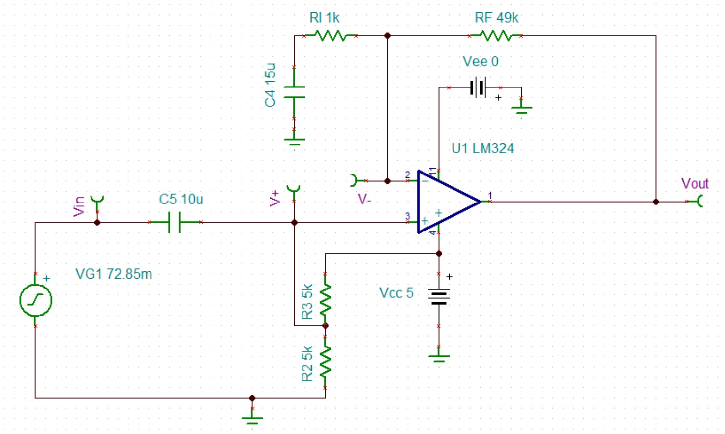
We want to amplify the small PWM signal, the circuit is shown in the picture. The simulated result shows that the output voltage is not always the PWM signal, it seems that the inverting input of LM324 is not equal to the non-inverting input.

However, if LM324 is changed to TLV9061, the output is PWM signal as expected, could you please help advise the reason why LM324 output voltage is not always PWM? Thanks!

0383.LM324.TSC

Best Regards!

Hao

  • Hao,

    Your signal is too big for the gain setting.

    Input is 68.15mV peak. The DC bias point is 2.5V. Gain is 50. So the VOH should be  2.5V + 50*68.15mV = 5.908 V. That is higher than the supply voltage and the VOH of LM324 is a little over VCC - 1.5V.  

    Input is 68.15mV peak. The DC bias point is 2.5V. Gain is 50. So the VOL should be  2.5V - 50*68.15mV = -0.908 V. That is lower than the ground voltage and the VOL of LM324.

    The inverting input won't be the same as non-inverting input when output clipping occurs.

  • Hi Ronald,

    The high gain is set on purpose. Yeah, the inverting input is not the same as non-inverting input when the output clipping occurs, however, if rail to rail input and output TLV9061 is used instead of LM324, the output is still PWM signal even when the output is clipping. Further more, changing the power supply to 3.3V for TLV9061, the output is PWM.

    I'm not sure why TLV9061 works while LM324 doesn't. Could you please help advise the possible reason, thanks!

    TLV9062 Circuit.TSC

    Best Regards!

    Hao

  • Hao,

    For TLV9061, 2.5V is the mid point between output low VOL and output high VOH so C4 stays in balance.

    For LM324 the mid point between VOH and VOL is not 2.5V so C4 gets a DC offset (so VOH is reached and VOL is not). To get a closer to 0V VOL on LM324, I suggest doubling RI and RF to drop feedback current from 40uA to 20uA (see the application note IOL and VOL section). That should give roughly 0.1V VOL and 3.5V VOH, the mid point is 1.8V so set positive input to that voltage.

    If you want VOL and VOH, just connect the inputs like a comparator with no feedback. That will make is more simple.

    Design Guidelines for Devices with LM324/LM358 Cores