This thread has been locked.

If you have a related question, please click the "Ask a related question" button in the top right corner. The newly created question will be automatically linked to this question.

OPA552: 2nd order low pass filter

Part Number: OPA552
Other Parts Discussed in Thread: TINA-TI, OPA551, OPA683

Hello, 

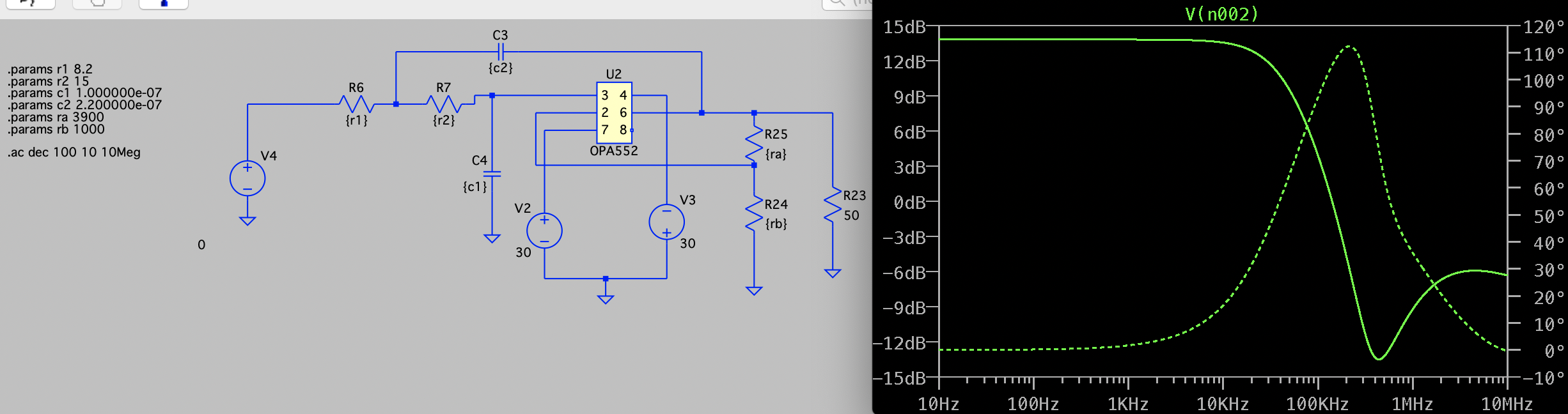
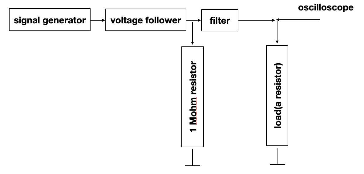
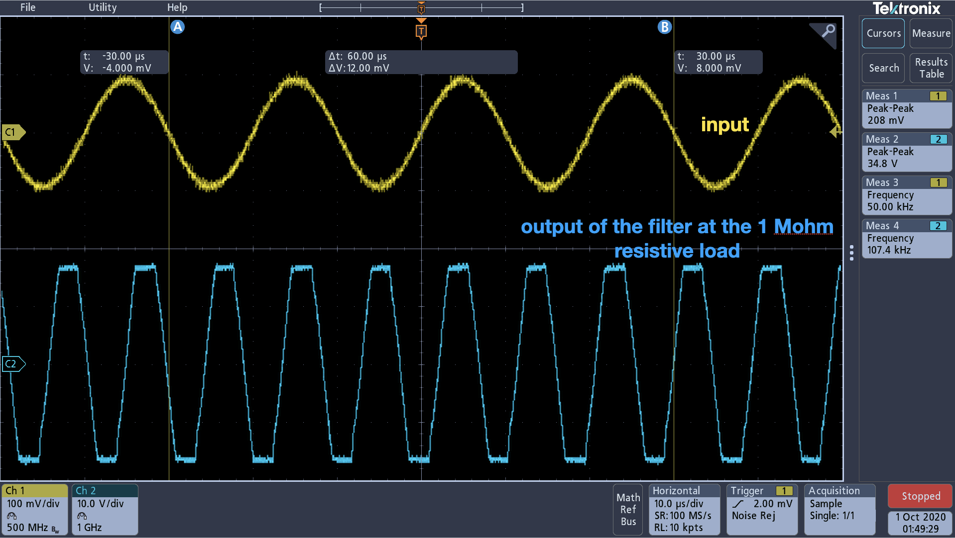
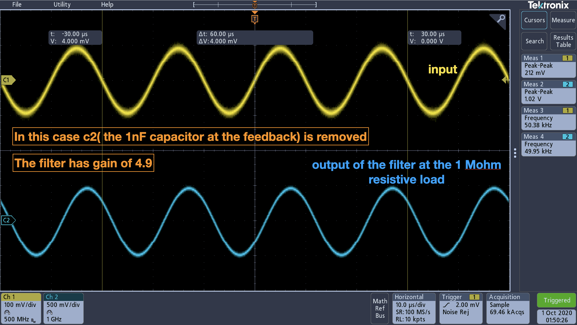
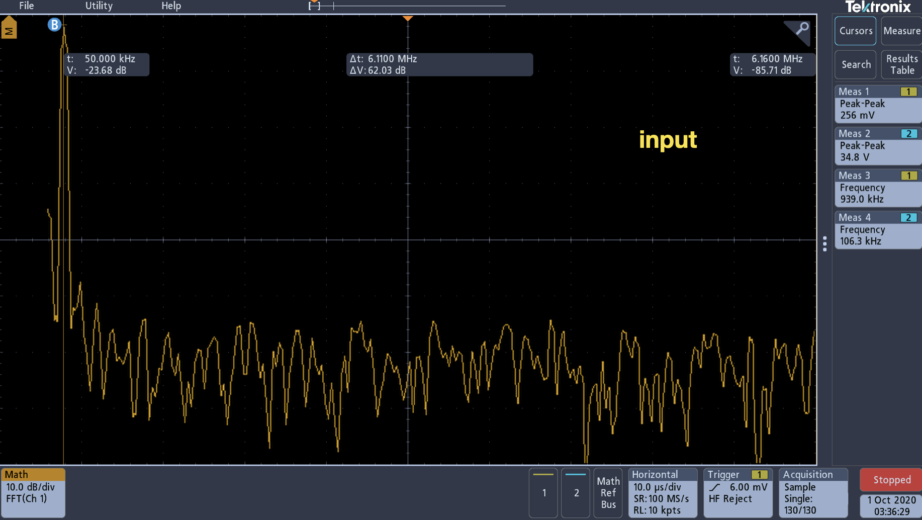
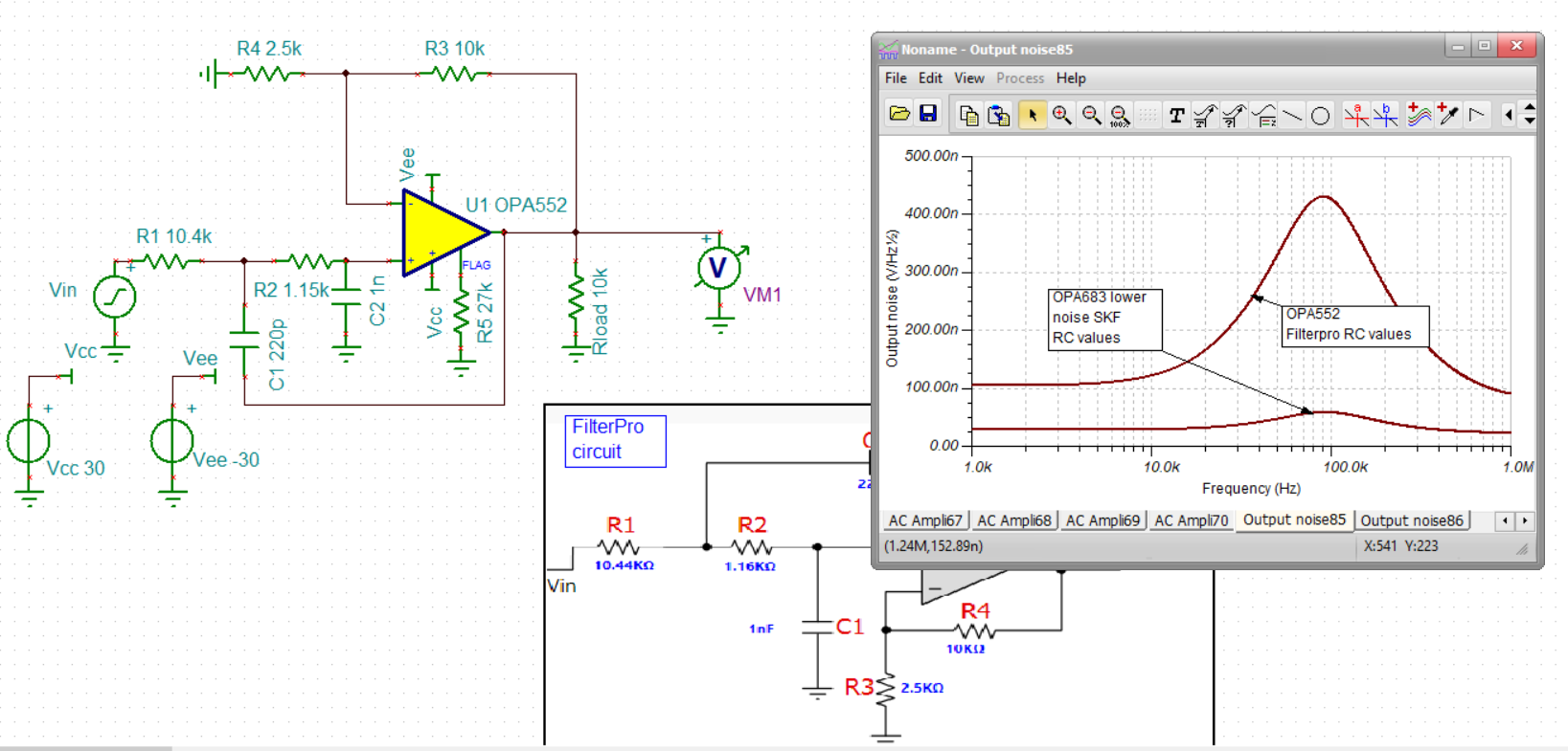
I am using OPA552 to make a 2nd order sallen key low pass filter. The LTSpice simulation shows stable results, however after implementing the hardware the output shows a high frequency noise. I am attaching the oscilloscope output where the yellow graph is the input and the blue graph is the output. The target cut-off frequency is 100 KHz, and the gain is around 5. I tried a higher load, around 1 Mohm and observed the same results. Also, the IC works fine as an amplifier (without filtering). 

I was wondering if you could comment on how I can solve this issue. Thank you. 

  • Oh my gosh those are low filter R values - sure you source can drive those? 

    Also, you need to show the R24 and R25 values - how are you probing? You show 50ohm load, but is this a cable to a 50ohm scope perhaps? 

  • Hello Mahsa,

    To Michael's point the input resistors in the Sallen-Key low-pass are extremely low in value compared to what are commonly applied. Normally these resistors are at a minimum in the hundreds of Ohms, but more often in kilohms, or tens-of kilohms. Unless the input source has an impedance close to zero ohms they will load the input source modifying the filter gain and phase characteristics, and also load the output excessively. The actual OPA552 may behave differently than the model under such conditions.

    Oscillation indicates that the phase margin of the circuit has been degraded to the point where it has reached zero degrees. As Michael pointed out there are the questions of the load on the OPA552 output. If the output is connected to a cable and instrument input, and the cable isn't properly terminated, it will appear as a capacitive load to the OPA552 which will degrade the phase margin. Please provide a schematic of the circuit including the input source, output load and any cabling used between them.

    Regards, Thomas

    Precision Amplifiers Applications Engineering

  • Also Mahsa, 

    your scope shot clearly shows an oscillation - as long as you have this set up, you might try feeding that signal into a spectrum analyzer to pull out the frequency terms in the oscillation. 

  • Hello Thomas and Michael, 

    Thanks for the recommendations. 

    I redesigned the filter in a way that the resistors values fall in the range that you recommended. I still see the same results. 

    As for the load, I use a 1 Mohm resistive load, I am attaching a block diagram here. 

    For all the cases so far when I remove c2(1nF), the capacitive load at the feedback of the filter, the output gets stable. This happens because the circuit simply changes to a non-inverting amplifier when I remove c2.  I am attaching the output of the filter with and without c2 here. 

  • Also, here are the fft plots attached. Thank you. 

  • Without running any sims, I would say your feedback and gain elements are way too high, introducing a feedback pole with the inverting input C. 

    Scale those down by a factor of 1000 and see if that helps.

  • Hello Mahsa,

    Okay, the new RC values look much better for a 94 kHz Sallen-Key low-pass having a gain of approximately 14 dB in the passband. When I simulate the circuit in our TINA-TI simulator the results look good, but I understand you are still having a stability issue.

    The OPA552 is an undercompensated op amp and is not unity gain stable (G = 1 V/V), but should be stable for gains of 5 V/V (14 dB) or greater. I expect that to be the case for a standard inverting, or non-inverting amplifier circuit for a noise gain >= 5 V/V as you confirmed by removing the feedback capacitor. However, when used in an active filter circuit such as the Sallen-Key there is both negative and positive feedback at work and the positive feedback may be decreasing the phase margin to the point where the circuit becomes unstable. It may be able to compensate the OPA552, but then that added compensation will modify the gain/phase response and alter the filter response you are attempting to achieve.

    I suggest trying the OPA551 in the circuit. It is unity gain stable and when I simulate it in your 94 kHz Sallen-Key filter the response is identical to the simulated result for the OPA552 (see below). My thought is the OPA551 being unity-gain stable has more phase margin compared to the OPA552 in the same circuit. If you decide to try that, do let us know if that results in stability.

    Regards, Thomas

    Precision Amplifiers Applications Engineering

  • Morning Tom and Mahsa, 

    I was trying to reactivate an old SKF design file I did for the Intersil online tools, no luck so far, but here is the Filterpro design for a 97kHz gain of 5 Butterworth, quite different RC selections you will note. Also Tom, the piece of my tool that is working says the OPA552 decomp part is barely fast enough for this design, the unity gain stable OPA551 at 3MHz GBP will only be 600kHz closed loop - really not enough for a 94kHz.  design. Also note the rejection goes flat above 10MHz, that is pretty normal for SKF as the input feeds through the feedback cap and is not sunk by the out of band higher output Z for the op amp. If, by chance, you had a higher F signal in your input you were trying to reject, maybe that is what you are seeing that looks like an oscillation. 

    Also Mahsa, we have not talked about large signal requirements, but if you are really using a +/-30V part for large output swing, let's check slew rate - say you need 50kHz +/-25V swing (you fill in actual numbers). That signal will required a SR of 8V/usec, the OPA552 has 24V/usec so would seem fine, the OPA551 is 15V/usec - so ok. If harmonic distortion is important, you will need more SR margin than this. 

  • Hello Mahsa,

    Considering Michael's valid points about the OPA551/OPA552 gain-bandwidths, can you tell us the maximum output voltage and current required from the filter stage?

    Regards, Thomas

    Precision Amplifiers Applications Engineering

  • Hello, 

    The maximum power that my receiver can take is 10 dBm. A signal between 500 mV and 1 V on a 50 ohm load is what we need. This leads to a current value of 10mA to 20 mA. 

    Also, for a 1 V signal with a carrier frequency of 100 KHz, the slew rate should be above 0.628 V/us. Since OPA552 has a slew rate of 24 V/us it seemed to be a good candidate for our application. 

    Best, 

    Mahsa 

  • Well Mahsa, 

    That is pretty modest swing requirements, you could easily do this this with +/-5V parts and much lower quiescent current. There are many options in that case, I would myself be trying an OPA683 being a current feedback person (and yes, CFA will work in SKF, odd that the literature sometimes says no to that, and, the Filterpro and other TI tools do not allow that option - I did allow that option in the Intersil tools). 

    Going further, 

    1. Can you be AC coupled? If so, doing a single 5V solution might be possible

    2. is there any noise or harmonic distortion needs? 

  • Morning Mahsa, 

    I was able to recover a working version of my SKF design tool, running that with the 1mA OPA683 gave this solution - the flows are trying to reduce R's to reasonable levels to improve the noise - this is a +/-5V design, but maybe could be single 5V is we can AC couple the input. Since the part is so low power, and the model is very good, the loss of stop band rejection common with SKF shows up above 3MHz. Faster parts, or an MFB design, would fix this if need be. 

     Here is this file, 

    OPA683 SKF version.TSC

  • Since I had both files open, easy to run an output spot noise comparison, 

    yes, the filterpro RC values with the OPA552 produce much higher output spot noise, that peaking around Fo is part of every active filter as the noise gain peaks around Fo, some designs more than others.