This thread has been locked.

If you have a related question, please click the "Ask a related question" button in the top right corner. The newly created question will be automatically linked to this question.

OPA548: Review two schematics on the case of capacitive load.

Part Number: OPA548

Hi,
I have three requests.

  1. I have set the current limit to 3A on OPA548. Is the current detected on the peak current or an average current? Please let me know.
  2.  My understanding is as follows: Is it correct? Please advise us.
    "When the current limit occurs, the output voltage is kept at 3A,. If current limit is released, it is normal output."
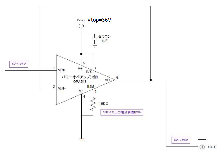
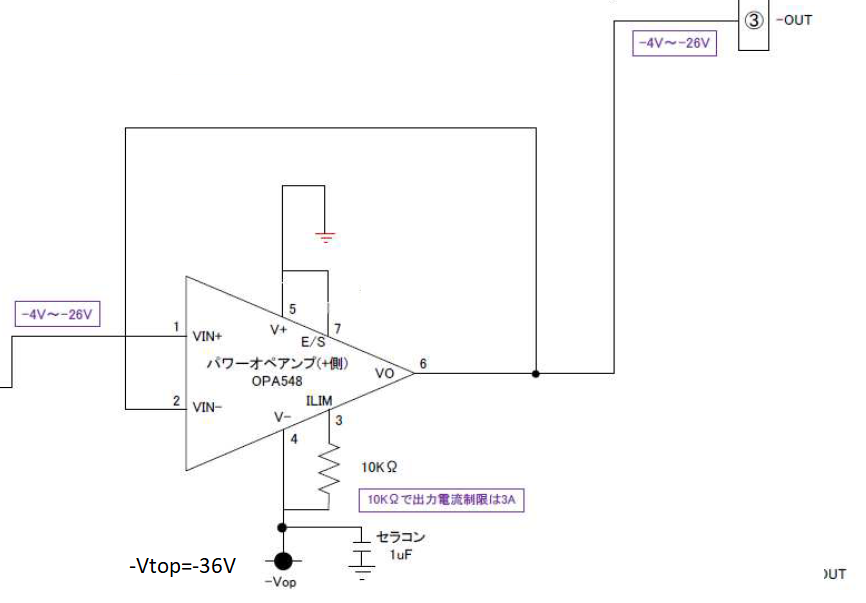
  3. My customer is designing the following two Voltage follower circuit.   Load of these circuits is capacitive.   Do you have any issues? Please advise us.

Case1:

Case2:

Thanks and best regards,
M.HATTORI

  • Hattori-san,

    Please see my responses to the questions about the OPA548 operation:

    1. I have set the current limit to 3A on OPA548. Is the current detected on the peak current or an average current? Please let me know.

      The Current Limit function, ILIM, is the peak current limit. Datasheet Figure 3, Current Limit vs Temperature and Figure 4, Current Limit vs Supply Voltage provide typical performance of this function.  

    2.  My understanding is as follows: Is it correct? Please advise us.
      "When the current limit occurs, the output voltage is kept at 3A,. If current limit is released, it is normal output."

      Yes, your understanding is correct. The maximum output current that can be delivered in this case is approximately 3 Amperes. If for example an output sine wave attempts to produce a 3.5 Ampere peak current it will be clipped when the peaks exceed +/-3 Amperes. 

    3. My customer is designing the following two Voltage follower circuit.   Load of these circuits is capacitive.   Do you have any issues? Please advise us.

    • Yes. Nearly all operational amplifiers have a limit to how much of a capacitive load (CLOAD) they can directly drive, remain stable and provide reasonably good transient response. That includes the OPA548. The buffer amplifier circuit (G = +1 V/V) as shown in your schematic are usually the most CLOAD sensitive application. However, with correct external compensation applied to the op amp circuit good stability and transient response can be achieved. You would need to understand the true output load impedance (R || -jXc) to perform an accurate stability analysis. A compensation plan can be determined from the results of the stability analysis.

    Regards, Thomas

    Precision Amplifiers Applications Engineering