This thread has been locked.
If you have a related question, please click the "Ask a related question" button in the top right corner. The newly created question will be automatically linked to this question.
Hi,
After repetitive tests and tweaks of settings as well as sensor position, I am not able to get a clean waveform from the Green LED and no sensible HR waveform from Red and IR, along the line of the following post:
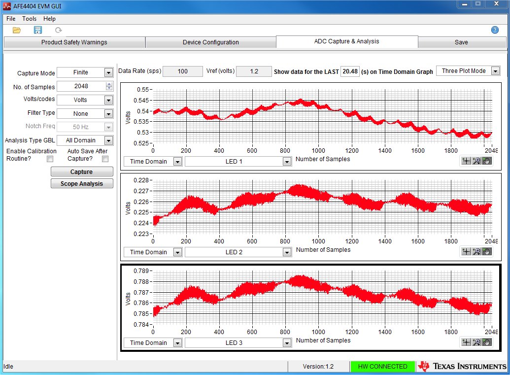
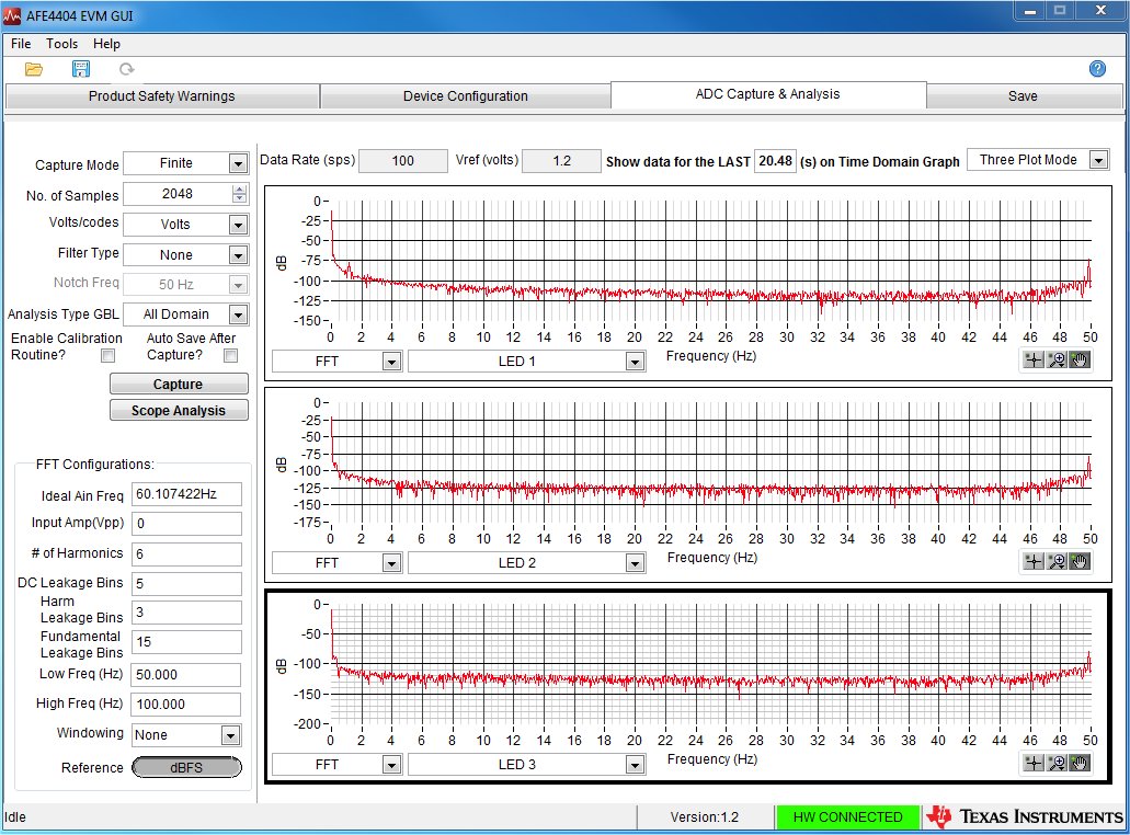
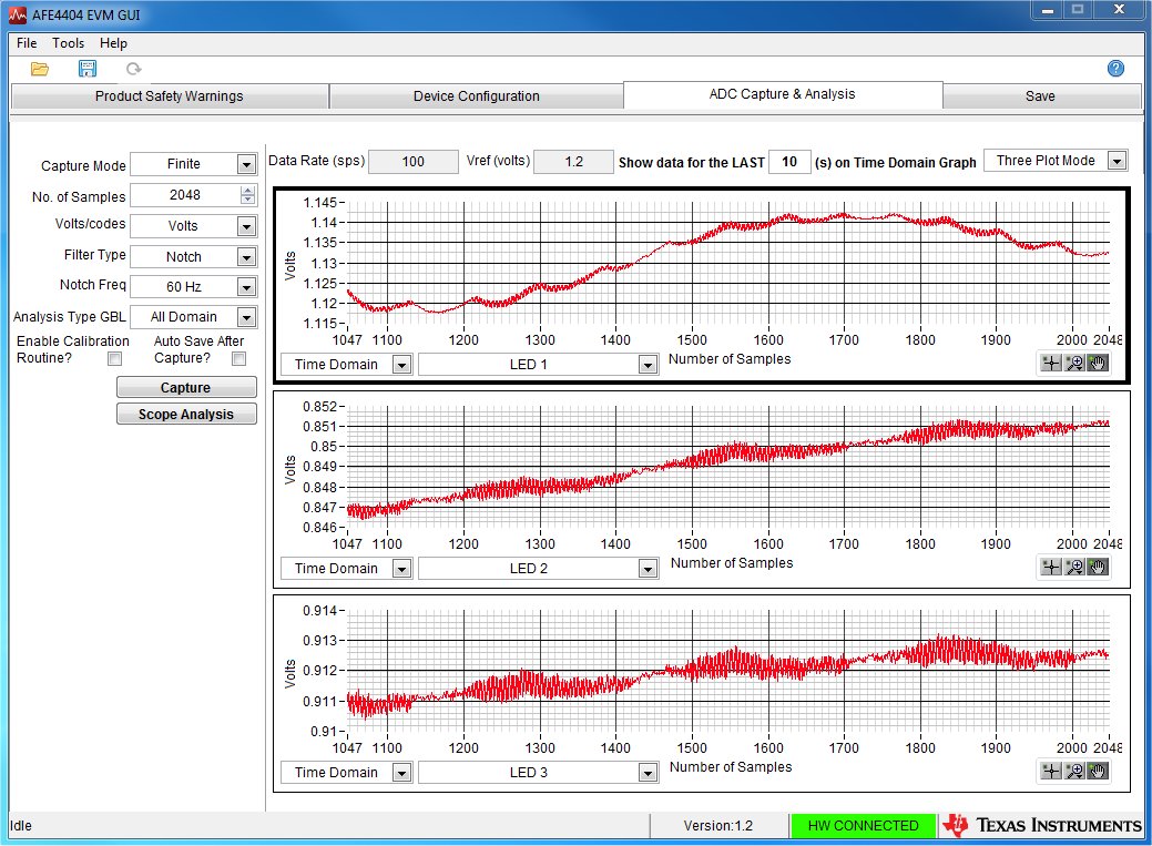
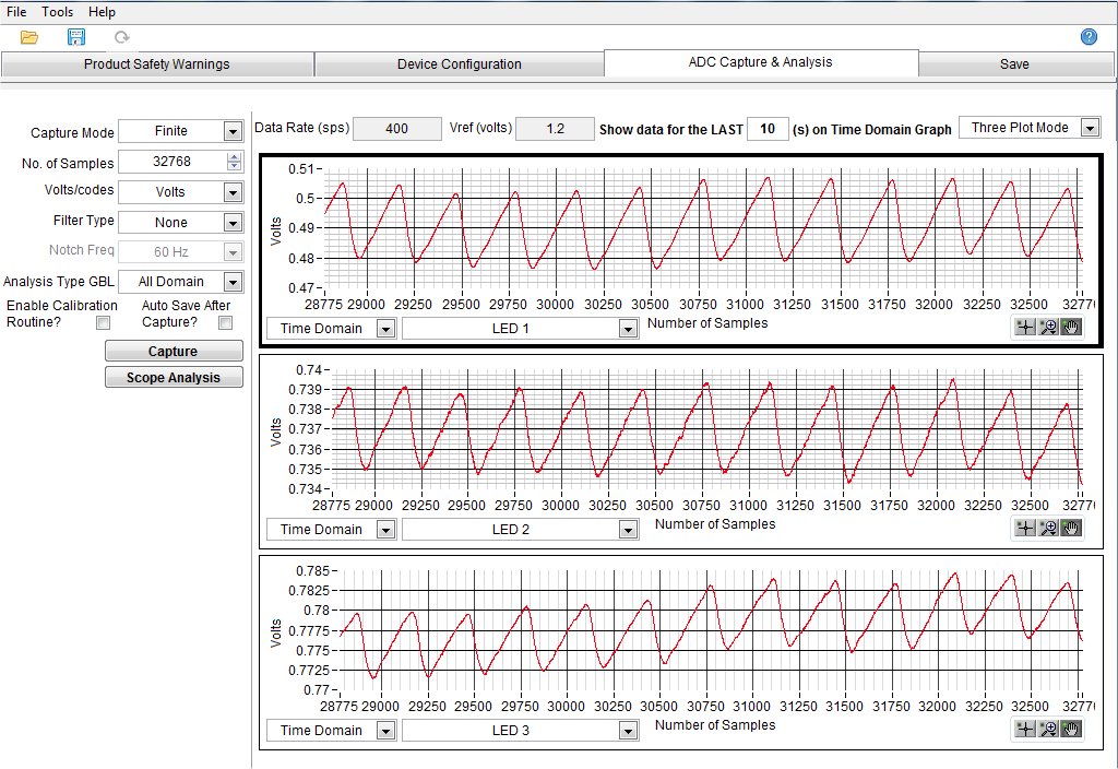
Please see screenshot attached for the LED1 (green), LED2 (red) and LED3 (infrared) waveforms I am getting.
Could you please advise how the sample waveform in figure 8 of the AFE4404 development guide was achieved, also in terms of settings? That looks very clean.
In detail, I am using the sensor board set for the NJRC sensor (default), with board covered in black insulating tape as suggested in the guide (just with a small opening for the NJRC sensor) and strapped on my "hairy" wrist with a Velcro strap held tightly.
I have left the TX settings as default (24mA green, 4.8mA red, 4.8mA infrared) and adjusted the offset and gain slightly in order to be around 1V on the output signal for all the 3 channels. The screenshot attached shows the signals below 1V since levels change depending on the sensor location on different days. So every time I keep the TX settings the same and adjust offset and gain for the 3 channels to be in range.
I have left the duty cycle as 1% (default) and sampling frequency as 100Hz (default). Increasing the averaging to 6 (from the default 3) or using the notch filter does not help much on the noise of the green, still showing no sensible HR waveform on red and infrared.
I attach here my configuration file as well as the saved logs.
Many thanks for your help.
Hi,
It seems like power line noise is interfering with the PPG signal acquisition.
You can also at the FFT of the output data and see if the noise is spread over frequency or concentrated in a single tone or set of tones.
We have come across situations where there was power line noise riding on top of the signal of interest.
Please refer to the E2E post below for few pointers to mitigate the problem.
https://e2e.ti.com/support/applications/medical/f/30/p/311809/1089207#1089207
Hi Praveen,
Many thanks for your advice.
My plan was to low pass filter the data offline (as per suggestion #3 of your suggested E2E post), but the raw data was really too noisy.
I have tried suggestion #2, i.e. applying the 50Hz/60Hz notch filter from within the guy, but that very little effect on the overall noise envelope.
I post here the time domain and FFT plots of what I am getting
As you can see, there is a slightly bit of more noise at 50Hz (my power line frequency) but in general the whole frequency spectrum up to 50Hz is noisy.
I then tried suggestion #1, i.e. no docking station and no AC/DC adapter. Here are the plots for that:
Noise is reduced overall (see FFT too) but still nowhere near figure 8 of the AFE4404 user guide... Any more advice there?
The above is valid for the green. Still for red and IR I seem to be getting no HR signal (lower noise there too but the waveforms do not really follow the green waveform in terms of periodicity). Any more advice there?
Many thanks again.
Hi Praveen,
an update on this: as well as the above I have also tried to increase the amount of averaging in the GUI, as well as increase the sample rate to 400Hz. Such a sample rate imposes me a duty cycle of 1.2% and a max averaging of 8 samples.
With these settings I get a green waveform clean enough for my post processing, which is good news.
Still the waveform from red and infrared do not follow the green one, not showing a recognisable HR waveform.
Best Regards
I have tried to place the Osram sensor on my forefinger and after tweaking the LED current way down for all the 3 LEDs I can now get PPG waveforms on all the 3 LEDs, which is very good news.
Only slight worry there is that with the forefinger I will be more prone to motion artefacts (for that the wrist measurement was great as I could use a strap held tightly).
I noticed the BMA280 footprint on the sensor board (instance U3). If I were to mount that, is the GUI/firmware set to take into account accelerometer data and subtract it from the PPG raw data so that what is viewed in the Capture tab of the GUI is motion compensated data?
Many Thanks