


Tool/software: TI-RTOS
Hi,
I am trying to bring up AR0220 sensor on my TDA2p. I have configured ser, deser. I am able to generate pattern from ser and deser. I am able to write in sensor's register.
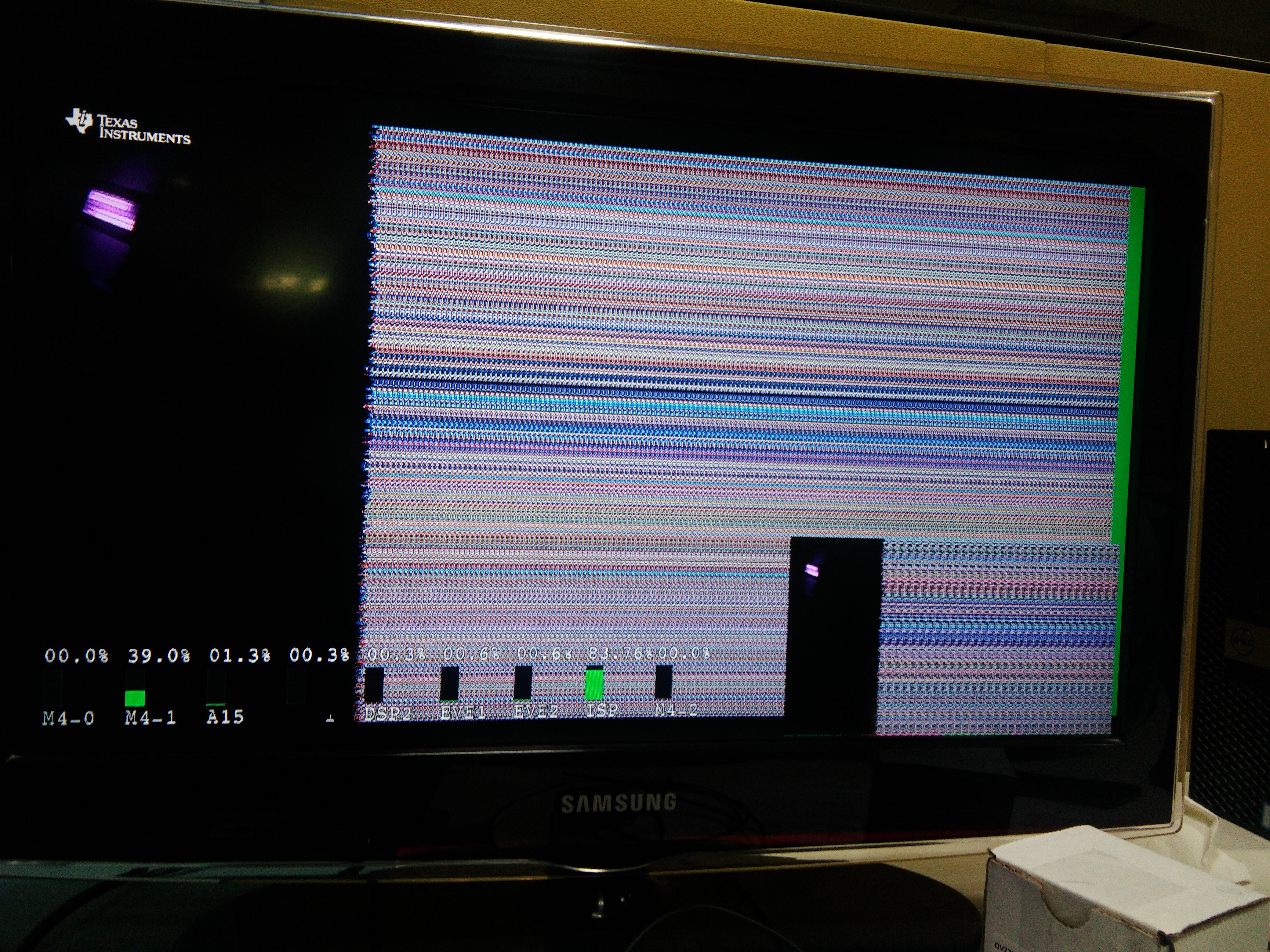
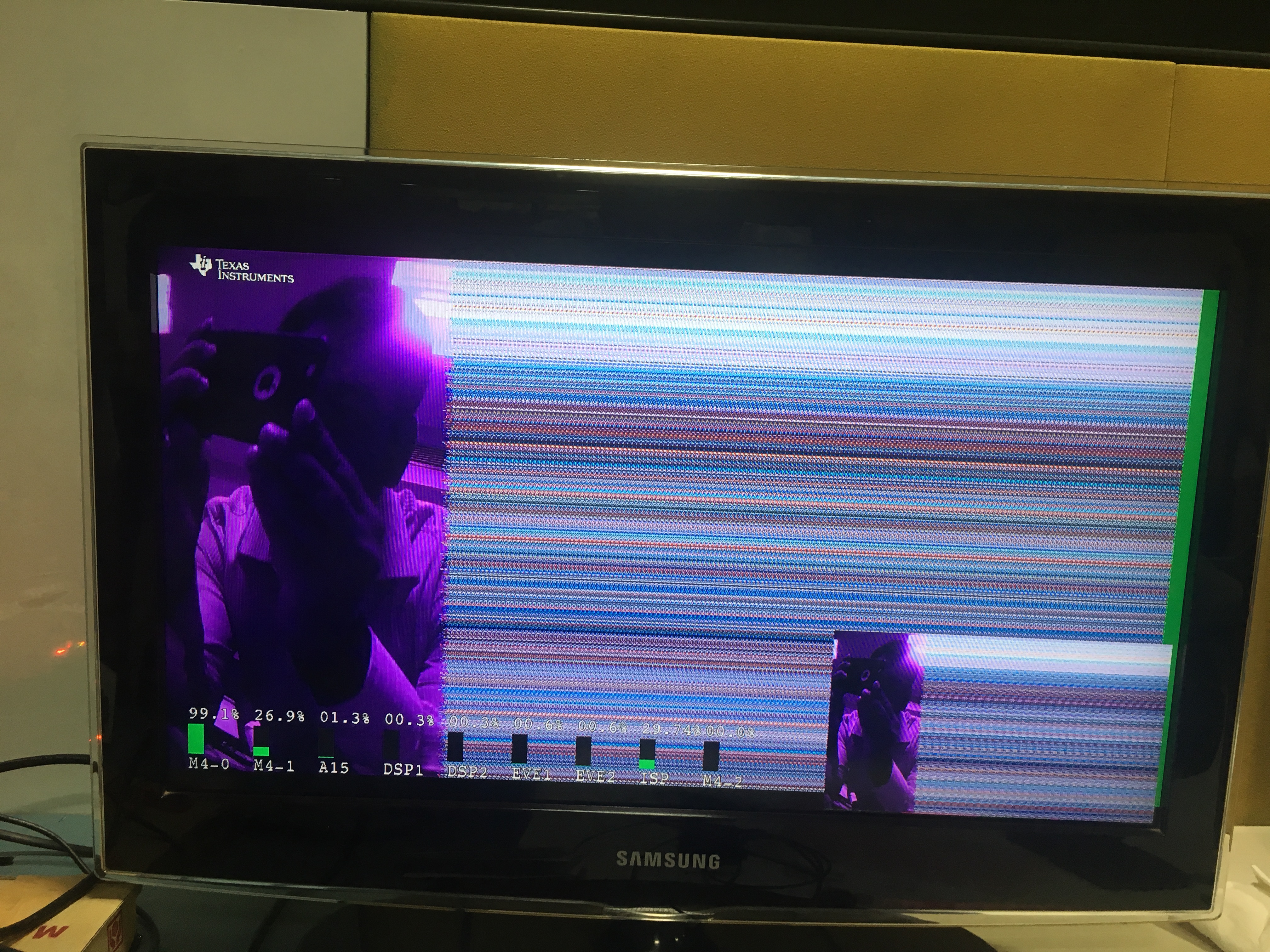
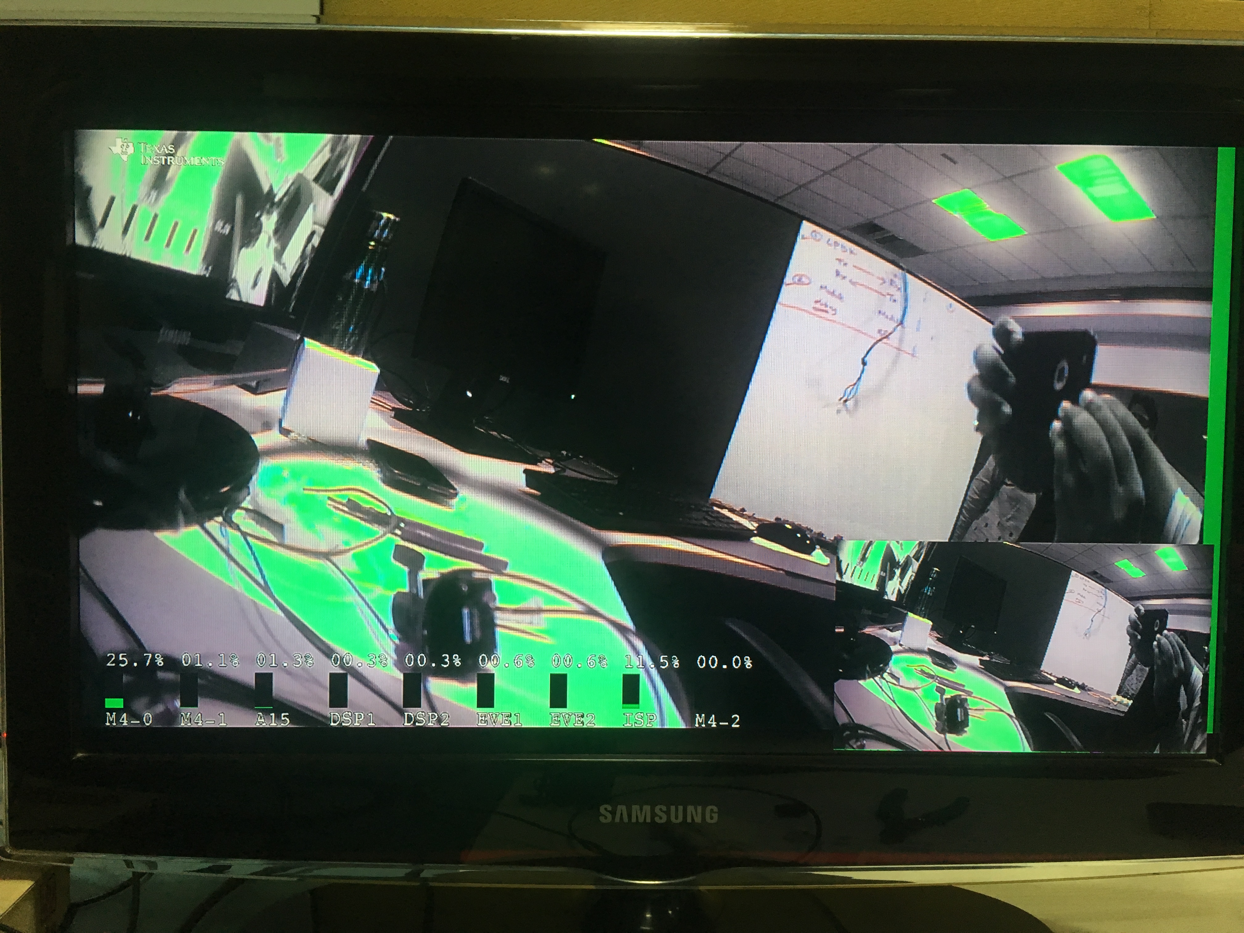
1) I am not getting any data from sensor.
Attached my sensor configurations.
2867.iss_sensor_tda2px.c
/******************************************************************************
Copyright (c) [2012 - 2017] Texas Instruments Incorporated
All rights reserved not granted herein.
Limited License.
Texas Instruments Incorporated grants a world-wide, royalty-free, non-exclusive
license under copyrights and patents it now or hereafter owns or controls to
make, have made, use, import, offer to sell and sell ("Utilize") this software
subject to the terms herein. With respect to the foregoing patent license,
such license is granted solely to the extent that any such patent is necessary
to Utilize the software alone. The patent license shall not apply to any
combinations which include this software, other than combinations with devices
manufactured by or for TI ("TI Devices"). No hardware patent is licensed
hereunder.
Redistributions must preserve existing copyright notices and reproduce this
license (including the above copyright notice and the disclaimer and
(if applicable) source code license limitations below) in the documentation
and/or other materials provided with the distribution
Redistribution and use in binary form, without modification, are permitted
provided that the following conditions are met:
* No reverse engineering, decompilation, or disassembly of this software
is permitted with respect to any software provided in binary form.
* Any redistribution and use are licensed by TI for use only with TI Devices.
* Nothing shall obligate TI to provide you with source code for the software
licensed and provided to you in object code.
If software source code is provided to you, modification and redistribution of
the source code are permitted provided that the following conditions are met:
* Any redistribution and use of the source code, including any resulting
derivative works, are licensed by TI for use only with TI Devices.
* Any redistribution and use of any object code compiled from the source code
and any resulting derivative works, are licensed by TI for use only with TI
Devices.
Neither the name of Texas Instruments Incorporated nor the names of its
suppliers may be used to endorse or promote products derived from this software
without specific prior written permission.
DISCLAIMER.
THIS SOFTWARE IS PROVIDED BY TI AND TI�S LICENSORS "AS IS" AND ANY EXPRESS OR
IMPLIED WARRANTIES, INCLUDING, BUT NOT LIMITED TO, THE IMPLIED WARRANTIES OF
MERCHANTABILITY AND FITNESS FOR A PARTICULAR PURPOSE ARE DISCLAIMED.
IN NO EVENT SHALL TI AND TI�S LICENSORS BE LIABLE FOR ANY DIRECT, INDIRECT,
INCIDENTAL, SPECIAL, EXEMPLARY, OR CONSEQUENTIAL DAMAGES (INCLUDING, BUT NOT
LIMITED TO, PROCUREMENT OF SUBSTITUTE GOODS OR SERVICES; LOSS OF USE, DATA, OR
PROFITS; OR BUSINESS INTERRUPTION) HOWEVER CAUSED AND ON ANY THEORY OF
LIABILITY, WHETHER IN CONTRACT, STRICT LIABILITY, OR TORT (INCLUDING NEGLIGENCE
OR OTHERWISE) ARISING IN ANY WAY OUT OF THE USE OF THIS SOFTWARE, EVEN IF
ADVISED OF THE POSSIBILITY OF SUCH DAMAGE.
******************************************************************************/
/**
*******************************************************************************
* \file iss_sensor_tda2px.c
*
*
*
*******************************************************************************
*/
/*******************************************************************************
* INCLUDE FILES
*******************************************************************************
*/
/* Including system.h for Int32/UInt32 data type */
#include <include/link_api/system.h>
#include <iss_utils.h>
#include <ti/drv/vps/include/platforms/bsp_platform.h>
#include <ti/drv/vps/include/boards/bsp_board.h>
#include <ti/drv/vps/include/vps.h>
#include <ti/drv/vps/include/vps_capture.h>
#include <ti/drv/vps/include/devices/bsp_device.h>
#include <ti/drv/vps/examples/utility/bsputils_ub960.h>
#include <iss_sensors.h>
#include <iss_sensor_serdes.h>
#include <iss_utils.h>
/*******************************************************************************
* Defines
*******************************************************************************
*/
/* I2C Instance for the board Mux */
#define CHAINS_COMMON_TDA2PX_BOARD_MUX_I2C_INST (0U)
/* I2C Address of the board mux */
#define CHAINS_COMMON_TDA2PX_BOARD_MUX_I2C_ADDR (0x23U)
/*******************************************************************************
* Data Structures
*******************************************************************************
*/
typedef struct {
char name[ISS_SENSORS_MAX_NAME];
ChainsCommon_IssSensorIf info;
} ChainsCommon_SensorIntfInfo;
/*******************************************************************************
* Globals
*******************************************************************************
*/
const static IssUtils_Ub96xSerDesCfg gSensorSerDesInfo[] = {
{SENSOR_OMNIVISION_OV10640_CSI2, NULL, 0, NULL, 0, BSPUTILS_FPDCAMPOWERLEVEL_OFF, 0U},
{SENSOR_SONY_IMX224_CSI2, NULL, 0, NULL, 0, BSPUTILS_FPDCAMPOWERLEVEL_OFF, 0U},
{SENSOR_OMNIVISION_OV10640_IMI, gAppIssUtilsUb960Cfg_OV10640_IMI, OV10640_IMI_DES_CFG_SIZE,
gUB913_OV10640_IMI_SerCfg, OV10640_IMI_SER_CFG_SIZE,
BSPUTILS_FPDCAMPOWERLEVEL_12V0, 100U},
{SENSOR_APTINA_AR0140_TIDA262, gAppIssUtilsUb960Cfg_AR0140_TIDA0262_DesCfg, AR0140_TIDA0262_DES_CFG_SIZE,
gUB913_AR0140_TIDA0262_SerCfg, AR0140_TIDA0262_SER_CFG_SIZE,
BSPUTILS_FPDCAMPOWERLEVEL_12V0, 100U},
{SENSOR_OMNIVISION_OV2775_TIDA1130, gAppIssUtilsUb960Cfg_OV2775_TIDA1130_DesCfg, OV2775_TIDA1130_DES_CFG_SIZE,
gUB953_OV2775_TIDA1130_SerCfg, OV2775_TIDA1130_SER_CFG_SIZE,
BSPUTILS_FPDCAMPOWERLEVEL_12V0, 100U},
{SENSOR_OMNIVISION_OV2775_CSI2, NULL, 0, NULL, 0, BSPUTILS_FPDCAMPOWERLEVEL_OFF, 0U},
{SENSOR_SONY_IMX390_UB953_D3, gUB960DesCfg_D3IMX390, IMX390_D3_DES_CFG_SIZE,
gAppIssUtilsUB953SerCfg_D3IMX390, IMX390_D3_SER_CFG_SIZE,
BSPUTILS_FPDCAMPOWERLEVEL_12V0, 2000U},
{SENSOR_APTINA_AR0143_MARS, gAppIssUtilsUb960Cfg_MARS_AR0143,AR143_MARS_DES_CFG_SIZE,
gUB913MarsAR0143SerCfg, AR143_MARS_SER_CFG_SIZE,
BSPUTILS_FPDCAMPOWERLEVEL_12V0, 500U},
{SENSOR_AR0220, gAppIssUtilsUb954Cfg_AR0220_CSI2_DesCfg, AR0220_CSI2_DES_CFG_SIZE,
gUB953_AR0220_CSI2_SerCfg, AR0220_CSI2_SER_CFG_SIZE,
BSPUTILS_FPDCAMPOWERLEVEL_12V0, 500U},
};
const static ChainsCommon_SensorIntfInfo gSensorInterfaceInfo[] = {
{SENSOR_OMNIVISION_OV10640_CSI2,
{4u, {0x32}, {0x32}, FALSE, SYSTEM_VIFW_4LANES, SYSTEM_VIFM_SCH_CSI2,
SYSTEM_CSI2_RAW12 /* CSI2 DataFormat*/, 0 /*Virtual Channel Id*/,
0, /* Is CSI Enable Required in UB960 */
{TRUE /* isCplxCfgValid */,
{{FALSE, 2}, /* Clock Lane */
{FALSE, 1}, /* data1Lane */
{FALSE, 3}, /* data2Lane */
{FALSE, 4}, /* data3Lane*/
{FALSE, 5}},/* data4Lane */
400 /* csi2PhyClk */ }}},
{SENSOR_SONY_IMX224_CSI2,
{4u, {0x36}, {0x36}, FALSE, SYSTEM_VIFW_4LANES, SYSTEM_VIFM_SCH_CSI2,
SYSTEM_CSI2_RAW12 /* CSI2 DataFormat*/, 0 /*Virtual Channel Id*/,
0, /* Is CSI Enable Required in UB960 */
{TRUE /* isCplxCfgValid */,
{{FALSE, 2u}, /* Clock Lane */
{FALSE, 1u}, /* data1Lane */
{FALSE, 3u}, /* data2Lane */
{FALSE, 4u}, /* data3Lane*/
{FALSE, 5u}},/* data4Lane */
150u /* csi2PhyClk */ }}},
{SENSOR_OMNIVISION_OV10640_IMI,
{
4u, /* TDA3X EVM board uses I2C instance 1 */
{PORT_0_SENSOR_ADDR, PORT_1_SENSOR_ADDR, PORT_2_SENSOR_ADDR, PORT_3_SENSOR_ADDR}, /* Sensor alias address */
{PORT_0_SER_ADDR, PORT_1_SER_ADDR, PORT_2_SER_ADDR, PORT_3_SER_ADDR}, /* Serializer alias address */
TRUE, /* isMultiChannel */
SYSTEM_VIFW_4LANES, SYSTEM_VIFM_SCH_CSI2,
SYSTEM_CSI2_RAW12 /* CSI2 DataFormat*/,
0 /*Virtual Channel Id*/,
0, /* Is CSI Enable Required in UB960 */
{TRUE /* isCplxCfgValid */,
{{FALSE, 1}, /* Clock Lane */
{FALSE, 2}, /* data1Lane */
{FALSE, 3}, /* data2Lane */
{FALSE, 4}, /* data3Lane*/
{FALSE, 5}},/* data4Lane */
800 /* csi2PhyClk */ },
FVID2_VID_SENSOR_IMI_OV10640_DRV, /* sensorDrvId */
TRUE, /* sensorBroadcast */
TRUE}}, /* enableFsin */
{SENSOR_APTINA_AR0140_TIDA262,
{
4u, /* TDA3X EVM board uses I2C instance 1 */
{PORT_0_SENSOR_ADDR, PORT_1_SENSOR_ADDR, PORT_2_SENSOR_ADDR, PORT_3_SENSOR_ADDR}, /* Sensor alias address */
{PORT_0_SER_ADDR, PORT_1_SER_ADDR, PORT_2_SER_ADDR, PORT_3_SER_ADDR}, /* Serializer alias address */
TRUE, /* isMultiChannel */
SYSTEM_VIFW_4LANES, SYSTEM_VIFM_SCH_CSI2,
SYSTEM_CSI2_RAW12 /* CSI2 DataFormat*/,
0 /*Virtual Channel Id*/,
0, /* Is CSI Enable Required in UB960 */
{TRUE /* isCplxCfgValid */,
{{FALSE, 1}, /* Clock Lane */
{FALSE, 2}, /* data1Lane */
{FALSE, 3}, /* data2Lane */
{FALSE, 4}, /* data3Lane*/
{FALSE, 5}},/* data4Lane */
800 /* csi2PhyClk */ },
FVID2_VID_SENSOR_TIDA00262_APT_AR0140_DRV, /* sensorDrvId */
FALSE, /* sensorBroadcast */
FALSE}}, /* enableFsin */
{SENSOR_OMNIVISION_OV2775_TIDA1130,
{
4u, /* TDA3X EVM board uses I2C instance 1 */
{PORT_0_SENSOR_ADDR,
PORT_1_SENSOR_ADDR,
PORT_2_SENSOR_ADDR,
PORT_3_SENSOR_ADDR,
PORT_4_SENSOR_ADDR,
PORT_5_SENSOR_ADDR,
PORT_6_SENSOR_ADDR,
PORT_7_SENSOR_ADDR}, /* Sensor alias address */
{PORT_0_SER_ADDR,
PORT_1_SER_ADDR,
PORT_2_SER_ADDR,
PORT_3_SER_ADDR,
PORT_4_SER_ADDR,
PORT_5_SER_ADDR,
PORT_6_SER_ADDR,
PORT_7_SER_ADDR}, /* Serializer alias address */
TRUE, /* isMultiChannel */
SYSTEM_VIFW_4LANES,
SYSTEM_VIFM_SCH_CSI2,
SYSTEM_CSI2_RAW12 /* CSI2 DataFormat*/,
0 /*Virtual Channel Id*/,
0, /* Is CSI Enable Required in UB960 */
{{TRUE /* isCplxCfgValid */,
{{FALSE, 1}, /* Clock Lane */
{FALSE, 2}, /* data1Lane */
{FALSE, 3}, /* data2Lane */
{FALSE, 4}, /* data3Lane*/
{FALSE, 5}},/* data4Lane */
800 /* csi2PhyClk */ },
{TRUE /* isCplxCfgValid */,
{{FALSE, 1}, /* Clock Lane */
{FALSE, 2}, /* data1Lane */
{FALSE, 3}, /* data2Lane */
{FALSE, 0}, /* data3Lane*/
{FALSE, 0}},/* data4Lane */
800 /* csi2PhyClk */ }},
FVID2_VID_SENSOR_OV2775_TIDA1130_DRV, /* sensorDrvId */
FALSE, /* sensorBroadcast */
FALSE, /* enableFsin */
{0x3d, 0x36}}},
{SENSOR_OMNIVISION_OV2775_CSI2,
{4u, {0x36}, {0x36}, FALSE, SYSTEM_VIFW_4LANES, SYSTEM_VIFM_SCH_CSI2,
SYSTEM_CSI2_RAW12 /* CSI2 DataFormat*/, 0 /*Virtual Channel Id*/,
0, /* Is CSI Enable Required in UB960 */
{TRUE /* isCplxCfgValid */,
{{FALSE, 3}, /* Clock Lane */
{FALSE, 4}, /* data1Lane */
{FALSE, 2}, /* data2Lane */
{FALSE, 0}, /* data3Lane*/
{FALSE, 0}},/* data4Lane */
480 /* csi2PhyClk */ }}},
{SENSOR_SONY_IMX390_UB953_D3,
{
4u, /* TDA3X EVM board uses I2C instance 1 */
{PORT_0_SENSOR_ADDR, PORT_1_SENSOR_ADDR, PORT_2_SENSOR_ADDR, PORT_3_SENSOR_ADDR}, /* Sensor alias address */
{PORT_0_SER_ADDR, PORT_1_SER_ADDR, PORT_2_SER_ADDR, PORT_3_SER_ADDR}, /* Serializer alias address */
TRUE, /* isMultiChannel */
SYSTEM_VIFW_4LANES, SYSTEM_VIFM_SCH_CSI2,
SYSTEM_CSI2_RAW12 /* CSI2 DataFormat*/,
0 /*Virtual Channel Id*/,
1, /* Is CSI Enable Required in UB960 */
{TRUE /* isCplxCfgValid */,
{{FALSE, 1}, /* Clock Lane */
{FALSE, 2}, /* data1Lane */
{FALSE, 3}, /* data2Lane */
{FALSE, 4}, /* data3Lane*/
{FALSE, 5}},/* data4Lane */
800 /* csi2PhyClk */ },
FVID2_VID_SENSOR_D3_SONY_IMX390_DRV, /* sensorDrvId */
FALSE, /* sensorBroadcast */
FALSE}, /* enable Fsin */
},
{SENSOR_APTINA_AR0143_MARS,
{
4u, /* TDA3X EVM board uses I2C instance 1 */
{PORT_0_SENSOR_ADDR, PORT_1_SENSOR_ADDR, PORT_2_SENSOR_ADDR, PORT_3_SENSOR_ADDR}, /* Sensor alias address */
{PORT_0_SER_ADDR, PORT_1_SER_ADDR, PORT_2_SER_ADDR, PORT_3_SER_ADDR}, /* Serializer alias address */
TRUE, /* isMultiChannel */
SYSTEM_VIFW_4LANES, SYSTEM_VIFM_SCH_CSI2,
SYSTEM_CSI2_RAW12 /* CSI2 DataFormat*/,
0 /*Virtual Channel Id*/,
0, /* IsCSIPostEnable Required */
{TRUE /* isCplxCfgValid */,
{{FALSE, 1}, /* Clock Lane */
{FALSE, 2}, /* data1Lane */
{FALSE, 3}, /* data2Lane */
{FALSE, 4}, /* data3Lane*/
{FALSE, 5}},/* data4Lane */
800 /* csi2PhyClk */ },
FVID2_VID_SENSOR_MARS_APT_AR0143_DRV, /* sensorDrvId */
FALSE, /* sensorBroadcast */
FALSE}}, /* enableFsin */
/**
* @TODO AR0220 sensor address to be updated
*/
//swati: Change this if required
{SENSOR_AR0220,
{
4u, /* I2C Instance id for the sensor */
{0x40}, /* I2C Address of the sensor */
{0x74}, /* I2C Address of the serializer */
TRUE, /* Flag for single/multi channel sensor config */
SYSTEM_VIFW_4LANES, /* Interface width */
SYSTEM_VIFM_SCH_CSI2, /* Video Interface mode - Single channel capture via CSI2 interface */
SYSTEM_CSI2_RAW12, /* Input CSI2 Data Format */
0, /* Virtual Channel Id */
1, /* Is CSI Enable Required in UB954 */
{TRUE /* isCplxCfgValid */,
{{FALSE, 1}, /* Clock Lane */
{FALSE, 2}, /* data1Lane */
{FALSE, 3}, /* data2Lane */
{FALSE, 4}, /* data3Lane*/
{FALSE, 5}},/* data4Lane */
800 /* csi2PhyClk */ },
FVID2_VID_SENSOR_AR0220_DRV, /* sensorDrvId */
FALSE, /* sensorBroadcast */
FALSE, /* enableFsin */
{0x30}}}
};
/*******************************************************************************
* Local Functions Declarations
*******************************************************************************
*/
/*******************************************************************************
* Function Definition
*******************************************************************************
*/
Int32 ChainsPlatform_GetSensorSerDesCfg(char name[],
IssUtils_Ub96xSerDesCfg* cfg)
{
Int32 status = SYSTEM_LINK_STATUS_EFAIL;
UInt32 cnt, numSensors;
UTILS_assert(NULL != cfg);
numSensors = sizeof(gSensorSerDesInfo)/sizeof(IssUtils_Ub96xSerDesCfg);
for (cnt = 0u; cnt < numSensors; cnt ++)
{
if (0 == strncmp(name, gSensorSerDesInfo[cnt].name,
ISS_SENSORS_MAX_NAME))
{
cfg->desCfgScript = gSensorSerDesInfo[cnt].desCfgScript;
cfg->num_des_registers= gSensorSerDesInfo[cnt].num_des_registers;
cfg->serCfgScript = gSensorSerDesInfo[cnt].serCfgScript;
cfg->num_ser_registers= gSensorSerDesInfo[cnt].num_ser_registers;
cfg->cam_pwr_level = gSensorSerDesInfo[cnt].cam_pwr_level;
cfg->waitAfterPowerOn = gSensorSerDesInfo[cnt].waitAfterPowerOn;
status = SYSTEM_LINK_STATUS_SOK;
break;
}
}
return (status);
}
Int32 ChainsPlatform_GetSensorIntfInfo(char name[],
ChainsCommon_IssSensorIf *info)
{
Int32 status = SYSTEM_LINK_STATUS_EFAIL;
UInt32 cnt, numSensors;
UTILS_assert(NULL != info);
numSensors = sizeof(gSensorInterfaceInfo)/sizeof(ChainsCommon_SensorIntfInfo);
for (cnt = 0u; cnt < numSensors; cnt ++)
{
if (0 == strncmp(name, gSensorInterfaceInfo[cnt].name,
ISS_SENSORS_MAX_NAME))
{
info->i2cInstId = gSensorInterfaceInfo[cnt].info.i2cInstId;
info->i2cAddr[0] = gSensorInterfaceInfo[cnt].info.i2cAddr[0];
info->i2cAddr[1] = gSensorInterfaceInfo[cnt].info.i2cAddr[1];
info->i2cAddr[2] = gSensorInterfaceInfo[cnt].info.i2cAddr[2];
info->i2cAddr[3] = gSensorInterfaceInfo[cnt].info.i2cAddr[3];
info->i2cAddr[4] = gSensorInterfaceInfo[cnt].info.i2cAddr[4];
info->i2cAddr[5] = gSensorInterfaceInfo[cnt].info.i2cAddr[5];
info->i2cAddr[6] = gSensorInterfaceInfo[cnt].info.i2cAddr[6];
info->i2cAddr[7] = gSensorInterfaceInfo[cnt].info.i2cAddr[7];
info->i2cAddrSer[0] = gSensorInterfaceInfo[cnt].info.i2cAddrSer[0];
info->i2cAddrSer[1] = gSensorInterfaceInfo[cnt].info.i2cAddrSer[1];
info->i2cAddrSer[2] = gSensorInterfaceInfo[cnt].info.i2cAddrSer[2];
info->i2cAddrSer[3] = gSensorInterfaceInfo[cnt].info.i2cAddrSer[3];
info->i2cAddrSer[4] = gSensorInterfaceInfo[cnt].info.i2cAddrSer[4];
info->i2cAddrSer[5] = gSensorInterfaceInfo[cnt].info.i2cAddrSer[5];
info->i2cAddrSer[6] = gSensorInterfaceInfo[cnt].info.i2cAddrSer[6];
info->i2cAddrSer[7] = gSensorInterfaceInfo[cnt].info.i2cAddrSer[7];
info->isMultiChannel = gSensorInterfaceInfo[cnt].info.isMultiChannel;
info->videoIfWidth = gSensorInterfaceInfo[cnt].info.videoIfWidth;
info->videoIfMode = gSensorInterfaceInfo[cnt].info.videoIfMode;
info->inCsi2DataFormat =
gSensorInterfaceInfo[cnt].info.inCsi2DataFormat;
info->inCsi2VirtualChanNum =
gSensorInterfaceInfo[cnt].info.inCsi2VirtualChanNum;
info->csi2Prms[0] = gSensorInterfaceInfo[cnt].info.csi2Prms[0];
info->csi2Prms[1] = gSensorInterfaceInfo[cnt].info.csi2Prms[1];
info->sensorDrvId = gSensorInterfaceInfo[cnt].info.sensorDrvId;
info->sensorBroadcast = gSensorInterfaceInfo[cnt].info.sensorBroadcast;
info->enableFsin = gSensorInterfaceInfo[cnt].info.enableFsin;
info->isEnableCSIPostConfig =
gSensorInterfaceInfo[cnt].info.isEnableCSIPostConfig;
info->deserializerAddr[0] = gSensorInterfaceInfo[cnt].info.deserializerAddr[0];
info->deserializerAddr[1] = gSensorInterfaceInfo[cnt].info.deserializerAddr[1];
status = SYSTEM_LINK_STATUS_SOK;
break;
}
}
return (status);
}
Void ChainsPlatform_SetPinMux(char name[])
{
Int32 status;
UInt32 cnt, numSensors;
Bsp_BoardMode boardMode;
numSensors = sizeof(gSensorInterfaceInfo)/sizeof(ChainsCommon_IssSensorIf);
for (cnt = 0u; cnt < numSensors; cnt ++)
{
if ((0 == strncmp(name, gSensorInterfaceInfo[cnt].name,
ISS_SENSORS_MAX_NAME)) &&
(SYSTEM_VIFM_SCH_CPI == gSensorInterfaceInfo[cnt].info.videoIfMode))
{
switch (gSensorInterfaceInfo[cnt].info.videoIfWidth)
{
default:
boardMode = BSP_BOARD_MODE_NONE;
break;
case SYSTEM_VIFW_8BIT:
boardMode = BSP_BOARD_MODE_VIDEO_8BIT;
break;
case SYSTEM_VIFW_10BIT:
boardMode = BSP_BOARD_MODE_VIDEO_10BIT;
break;
case SYSTEM_VIFW_12BIT:
boardMode = BSP_BOARD_MODE_VIDEO_12BIT;
break;
case SYSTEM_VIFW_14BIT:
boardMode = BSP_BOARD_MODE_VIDEO_14BIT;
break;
case SYSTEM_VIFW_16BIT:
boardMode = BSP_BOARD_MODE_VIDEO_16BIT;
break;
case SYSTEM_VIFW_24BIT:
boardMode = BSP_BOARD_MODE_VIDEO_24BIT;
break;
}
/* Set pinmux */
status = Bsp_boardSetPinMux(FVID2_VPS_CAPT_VID_DRV,
VPS_CAPT_INST_ISS_CAL_A, boardMode);
UTILS_assert (SYSTEM_LINK_STATUS_SOK == status);
break;
}
}
}
Void ChainsBoard_SetBoardMux(char name[])
{
Int32 status;
UInt32 cnt, numSensors;
UInt8 regValue[3U];
numSensors = sizeof(gSensorInterfaceInfo)/sizeof(ChainsCommon_IssSensorIf);
for (cnt = 0u; cnt < numSensors; cnt ++)
{
if ((0 == strncmp(name, gSensorInterfaceInfo[cnt].name,
ISS_SENSORS_MAX_NAME)) &&
(SYSTEM_VIFM_SCH_CPI == gSensorInterfaceInfo[cnt].info.videoIfMode))
{
status = Bsp_boardReadTCA6424BoardMux(3, regValue);
UTILS_assert(status == BSP_SOK);
/* Select the CPI input by setting Mux Control 0 and 5 */
regValue[0u] |= (0x21);
/* Set VIN_MAP[0:2] to 010 for Aptina 12-bit - Level 2 */
regValue[2u] &= ~(0x3D);
status = Bsp_boardWriteTCA6424BoardMux(3, regValue);
UTILS_assert(status == BSP_SOK);
BspOsal_sleep(50);
break;
}
}
}
1854.iss_sensor_ar0220.c
/**
*******************************************************************************
* \file iss_sensor_ar0220.c
*
*
*
*******************************************************************************
*/
/*******************************************************************************
* INCLUDE FILES
*******************************************************************************
*/
#include <iss_sensor_if.h>
#include <iss_sensor_serdes.h>
/**< ISS AEWB plugin is included here to get the default AEWB configuration
from each sensor */
#include <algorithmLink_issAewb.h>
#include "ar0220_mars_linear_1820x940_setup.h"
#include "ar0220_mars_wdr_1820x940_setup.h"
#include "ar0220_gain_table.h"
#include "ar0220_dcc.h"
#include "ar0220_dcc_1pass.h"
#include <ti/drv/vps/include/devices/bsp_device.h>
/**< UB953 I2C Address */
#define UB953_I2C_ADDRESS (0x18)
/**< UB953 Alias I2C Address */
#define UB953_I2C_ALIAS_ADDRESS (0x74)
/**< OV7261 I2C Address */
#define AR0220_I2C_ADDRESS (0x10)
/**< OV7261 Alias I2C Address */
#define AR0220_I2C_ALIAS_ADDRESS (0x40)
BspUtils_Ub960I2cParams gAppIssUtilsUb954Cfg_AR0220_CSI2_DesCfg[AR0220_CSI2_DES_CFG_SIZE] = {
{0x0C, 0x83, 0x10}, // Change to 83 from 0F
{0x1F, 0x00, 0x10}, /* 1.6Gbps CSI Freq */
/*CAMERA 1*/
{0x4C, 0x01, 0x1}, /*Page FPD3 port RX0 registers for R/W*/
{0x58, 0x5D , 0x1}, /*Enable and set backchannel rate to 50Mbs / I2C passthrough enabled*/
{0x5C, 0x30, 0x1}, /*set serializer alias to Ox18 (7-bit)*/
{0x5D, ((uint8_t) (UB953_I2C_ADDRESS << 1U)), 0x0},
{0x65, ((uint8_t) (UB953_I2C_ALIAS_ADDRESS << 1U)), 0x0},
{0x5E, ((uint8_t) (AR0220_I2C_ADDRESS << 1U)), 0x0},
{0x66, ((uint8_t) (AR0220_I2C_ALIAS_ADDRESS << 1U)), 0x0},
{0x6D, 0x7C, 0x1}, /*CSI and coax mode*/
{0xD5, 0xF0, 0x1}, /* Set AEQ MIN/MAX widest values*/
{0x7C, 0x01, 0x1}, /*same as Omnivision*/
{0x70, 0x2B, 0x1}, /*same as Omnivision*/
{0x71, 0x2C, 0x1}, /*same as Omnivision*/
{0x72, 0xE4, 0x1}, /*same as Omnivision*/
{0x32, 0x01, 0x1}, /*CSI0 select*/
{0x33, 0x03, 0x1}, /*CSI_EN & CSI0 4L*/
{0x21, 0x03, 0x1},
{0x20, 0x00, 0x1},
{0xB9, 0x18, 0x1}, /*ENABLE PARITY ERROR COUNT*/
{0x42, 0x71, 0x1}, /*ENABLE S-Filter with AEQ*/
{0x10, 0x59, 0x1}, /*Output Frame on GPIO0 */
};
BspUtils_Ub960I2cParams gUB953_AR0220_CSI2_SerCfg[AR0220_CSI2_SER_CFG_SIZE] = {
//{0x02, 0x52, 0x10},
{0x32, 0xE9, 0x10},
{0x06, 0x21, 0x10},
{0x07, 0x28, 0x10},
// {0x0E, 0xF0, 0x10},
// {0x0D, 0x00, 0x10},
// {0x0D, 0x0C, 0x10},
{0x0E, 0xC0, 0x10},
{0x0D, 0x0C, 0x10},
{0x0D, 0x08, 0x10},
{0x0D, 0x0C, 0x10},
};
/*******************************************************************************
* Defines
*******************************************************************************
*/
#define ISS_SENSORS_AR0220_DEFAULT_EXP_RATIO (16U)
#define ISS_SENSORS_AR0220_FEATURES (ISS_SENSOR_FEATURE_LINEAR_MODE| \
ISS_SENSOR_FEATURE_ONE_PASS_WDR_MODE| \
ISS_SENSOR_FEATURE_TWO_PASS_WDR_MODE| \
ISS_SENSOR_FEATURE_MANUAL_EXPOSURE| \
ISS_SENSOR_FEATURE_MANUAL_GAIN| \
ISS_SENSOR_FEATURE_DCC_SUPPORTED)
/*******************************************************************************
* Data structure's
*******************************************************************************
*/
struct {
UInt32 maxCoarseIntgTime;
/**< Max Coarse integration time supported by sensor */
float lineIntgTimeInMs;
/**< Line Integration time in ms */
float pixIntgTimeInMs;
/**< Pixel Integration time in ms */
} gAr0220DeviceObj;
/*******************************************************************************
* Local Functions Declarations
*******************************************************************************
*/
static Int32 AR0220_Start(UInt32 chId, IssSensor_CreateParams *pCreatePrms);
static Int32 AR0220_MARS_Start(UInt32 chId, IssSensor_CreateParams *pCreatePrms);
static Int32 AR0220_Stop(UInt32 chId, IssSensor_CreateParams *pCreatePrms);
static Int32 AR0220_SetAeParams(IssSensor_CreateParams *pCreatePrms,
IssSensor_AeParams *pAePrms);
static Int32 AR0220_GetDccParams(IssSensor_CreateParams *pCreatePrms,
IssSensor_DccParams *pDccPrms);
static AR0220_GetExpParams(IssSensor_CreateParams *pCreatePrms,
IssSensor_ExposureParams *pExpPrms);
static Void AR0220_InitAewbConfig(
IssSensor_CreateParams *pCreatePrms,
AlgorithmLink_IssAewbCreateParams *pAewbPrms);
static Void AR0220_GetIspConfig (
IssSensor_CreateParams *pCreatePrms,
IssIspConfigurationParameters *pIspCfg);
static Int32 AR0220_ReadWriteReg (
IssSensor_CreateParams *pCreatePrms, UInt32 readWriteFlag,
IssSensor_ReadWriteReg *pReg);
static Int32 AR0220_ReadReg(UInt8 i2cInstId,
UInt8 i2cAddr,
const UInt16 *regAddr,
UInt16 *regVal,
UInt32 numRegs);
static Int32 AR0220_WriteReg(UInt8 i2cInstId,
UInt8 i2cAddr,
const UInt16 *regAddr,
const UInt16 *regVal,
UInt32 numRegs);
/*******************************************************************************
* Globals
*******************************************************************************
*/
/* \brief Sensor Params structure used for registering this sensor to chains_iss
*/
static IssSensorIf_Params SensorParams_Ar0220 = {0};
static const UInt8 gAr0220DccCfgLinearAndWdr[] = AR0220DCC_CFG;
static const UInt8 gAr0220DccCfgSinglePassWdr[] = AR0220_1PASSDCC_CFG;
static IssSensor_ConfigRegs gAR0220SensorsLinearConfig[] =
AR0220_MARS_LINEAR_1820X940_CONFIG;
static IssSensor_ConfigRegs gAR0220SensorsWdrConfig[] =
AR0220_MARS_WDR_1820X940_CONFIG;
static IssSensor_ConfigRegs gAR0220MarsSensorsLinearConfig[] =
AR0220_MARS_LINEAR_1820X940_CONFIG;
static IssSensor_ConfigRegs gAR0220MarsSensorsWdrConfig[] =
AR0220_MARS_WDR_1820X940_CONFIG;
static UInt32 gAr0220GainsTable[ISS_SENSORS_AR0220_ANALOG_MAX_GAIN][3] =
AR0220_GAIN_TABLE;
/**
* \brief Structure for ISP H3A AEWB engine parameters.
*/
static vpsissH3aAewbConfig_t aewbConfig_ar0220 =
{
FALSE, /* enableALowComp */
FALSE, /* enableMedFilt */
0xFFF, /* midFiltThreshold */
{ /* vpsissH3aPaxelConfig_t winCfg */
{320u, 280u}, /* Fvid2_PosConfig pos */
32u, /* width */
16u, /* height */
20u, /* horzCount */
20u, /* vertCount */
2, /* horzIncr */
2, /* vertIncr */
},
718u, /* Black Line Vertical Start */
2u, /* Black Line Width */
VPS_ISS_H3A_OUTPUT_MODE_SUM_ONLY, /* vpsissH3aOutputMode_t outMode; */
2, /* sumShift */
1023u, /* satLimit */
VPS_ISS_H3A_MODE_NORMAL /* vpsissH3aMode_t mode */
} ;
/**
* \brief Structure for ISP GLBCE WDR Params.
*/
static vpsissGlbceWdrConfig_t glbceWdrCfg_ar0220 =
{
TRUE,
{
0U,24U,64U,114U,172U,237U,307U,383U,464U,549U,638U,731U,828U,928U,
1031U,1138U,1248U,1361U,1477U,1596U,1717U,1841U,1967U,2096U,2228U,
2361U,2498U,2636U,2777U,2919U,3064U,3211U,3360U,3511U,3664U,3819U,
3976U,4134U,4295U,4457U,4622U,4787U,4955U,5125U,5296U,5468U,5643U,
5819U,5997U,6176U,6357U,6539U,6723U,6908U,7095U,7284U,7474U,7665U,
7858U,8052U,8248U,8445U,8644U,8843U,9045U,9247U,9451U,9656U,9863U,
10071U,10280U,10490U,10702U,10915U,11129U,11345U,11561U,11779U,11998U,
12219U,12440U,12663U,12887U,13112U,13338U,13566U,13794U,14024U,14255U,
14487U,14720U,14954U,15189U,15426U,15663U,15902U,16142U,16382U,16624U,
16867U,17111U,17356U,17602U,17849U,18097U,18346U,18596U,18847U,19099U,
19353U,19607U,19862U,20118U,20375U,20633U,20892U,21152U,21413U,21675U,
21938U,22202U,22467U,22732U,22999U,23267U,23535U,23805U,24075U,24346U,
24618U,24891U,25165U,25440U,25716U,25993U,26270U,26549U,26828U,27108U,
27389U,27671U,27954U,28238U,28522U,28807U,29094U,29381U,29669U,29957U,
30247U,30537U,30829U,31121U,31414U,31707U,32002U,32297U,32593U,32890U,
33188U,33487U,33786U,34086U,34387U,34689U,34992U,35295U,35599U,35904U,
36210U,36516U,36823U,37132U,37440U,37750U,38060U,38371U,38683U,38996U,
39309U,39623U,39938U,40254U,40570U,40887U,41205U,41523U,41843U,42163U,
42483U,42805U,43127U,43450U,43774U,44098U,44423U,44749U,45075U,45403U,
45731U,46059U,46389U,46719U,47049U,47381U,47713U,48046U,48379U,48714U,
49048U,49384U,49720U,50057U,50395U,50733U,51072U,51412U,51752U,52093U,
52435U,52777U,53121U,53464U,53809U,54154U,54499U,54846U,55193U,55540U,
55889U,56238U,56587U,56938U,57289U,57640U,57992U,58345U,58699U,59053U,
59408U,59763U,60119U,60476U,60833U,61191U,61550U,61909U,62269U,62629U,
62990U,63352U,63714U,64077U,64441U,64805U,65170U,65535U
}
};
/*******************************************************************************
* Function Definition
*******************************************************************************
*/
Void IssSensor_AR0220_Init()
{
Int32 status;
IssSensorIf_Params *prms = &SensorParams_Ar0220;
IssSensor_Info *info = &SensorParams_Ar0220.info;
IssSensorIf_Params_Init(prms);
strncpy(prms->name, SENSOR_AR0220, ISS_SENSORS_MAX_NAME);
prms->dccId = 143;
info->width = 1820;
info->height = 940;
info->dataFormat = SYSTEM_DF_BAYER_BGGR;
info->bpp = SYSTEM_BPP_BITS12;
info->features = ISS_SENSORS_AR0220_FEATURES;
info->aewbMode = ALGORITHMS_ISS_AEWB_MODE_AEWB;
info->maxExp = 1;
info->ramOffset = 24*1024*1024;
prms->start = AR0220_Start;
prms->stop = AR0220_Stop;
prms->setAeParams = AR0220_SetAeParams;
prms->getExpParams = AR0220_GetExpParams;
prms->getDccParams = AR0220_GetDccParams;
prms->initAewbConfig = AR0220_InitAewbConfig;
prms->getIspConfig = AR0220_GetIspConfig;
prms->readWriteReg = AR0220_ReadWriteReg;
status = IssSensorIf_RegisterSensor(prms);
UTILS_assert(SYSTEM_LINK_STATUS_SOK == status);
}
#if 1
Void IssSensor_AR0220_MARS_Init()
{
Int32 status;
IssSensorIf_Params *prms = &SensorParams_Ar0220;
IssSensor_Info *info = &SensorParams_Ar0220.info;
IssSensorIf_Params_Init(prms);
strncpy(prms->name, SENSOR_AR0220_MARS, ISS_SENSORS_MAX_NAME);
prms->dccId = 143;
info->width = 1820;
info->height = 940;
info->dataFormat = SYSTEM_DF_BAYER_BGGR;
info->bpp = SYSTEM_BPP_BITS12;
info->features = ISS_SENSORS_AR0220_FEATURES;
info->aewbMode = ALGORITHMS_ISS_AEWB_MODE_AEWB;
info->maxExp = 1;
info->ramOffset = 24*1024*1024;
prms->start = AR0220_MARS_Start;
prms->stop = AR0220_Stop;
prms->setAeParams = AR0220_SetAeParams;
prms->getExpParams = AR0220_GetExpParams;
prms->getDccParams = AR0220_GetDccParams;
prms->initAewbConfig = AR0220_InitAewbConfig;
prms->getIspConfig = AR0220_GetIspConfig;
prms->readWriteReg = AR0220_ReadWriteReg;
status = IssSensorIf_RegisterSensor(prms);
UTILS_assert(SYSTEM_LINK_STATUS_SOK == status);
}
#endif
/*******************************************************************************
* Local Functions Definition
*******************************************************************************
*/
static Int32 AR0220_Start(UInt32 chId, IssSensor_CreateParams *pCreatePrms)
{
Vps_printf("Bsp_deviceI2cProbeAll start.......\n");
Int32 retVal = Bsp_deviceI2cProbeAll(BSP_DEVICE_I2C_INST_ID_4);
if (retVal == BSP_SOK)
{
Vps_printf("Bsp_deviceI2cProbeAll is done...\n");
}
else {
Vps_printf("Bsp_deviceI2cProbeAll is failed...\n");
}
Int32 status = SYSTEM_LINK_STATUS_EFAIL;
UInt32 cnt, i2cInstId, features, numRegs;
UInt8 i2cAddr;
UInt16 regAddr, regValue;
IssSensor_ConfigRegs *sensorRegs;
UTILS_assert(NULL != pCreatePrms);
i2cInstId = pCreatePrms->i2cInstId;
i2cAddr = pCreatePrms->i2cAddr[chId];
features = pCreatePrms->enableFeatures[chId];
if (ISS_SENSOR_FEATURE_LINEAR_MODE ==
(features & ISS_SENSOR_FEATURE_LINEAR_MODE))
{
sensorRegs = gAR0220SensorsLinearConfig;
numRegs = sizeof(gAR0220SensorsLinearConfig)/
sizeof(IssSensor_ConfigRegs);
gAr0220DeviceObj.maxCoarseIntgTime = MAX_COARSE_INT_LINES_LINEAR_940P;
}
else
{
sensorRegs = gAR0220SensorsWdrConfig;
numRegs = sizeof(gAR0220SensorsWdrConfig)/
sizeof(IssSensor_ConfigRegs);
gAr0220DeviceObj.maxCoarseIntgTime = MAX_COARSE_INT_LINES_WDR_940P;
}
gAr0220DeviceObj.lineIntgTimeInMs = 40.9f;
gAr0220DeviceObj.pixIntgTimeInMs = 0.032f;
for (cnt = 0u; cnt < numRegs; cnt ++)
{
regAddr = sensorRegs[cnt].regAddr;
regValue = sensorRegs[cnt].regValue;
/* Convert Registers address and value into 8bit array */
status = AR0220_WriteReg(i2cInstId, i2cAddr, ®Addr,
®Value, 1u);
if (SYSTEM_LINK_STATUS_SOK != status)
{
Vps_printf("AR0220_Start : status = %x\n", status);
Vps_printf("AR0220_WriteReg FAILED : Reg Addr = %x, Reg Val = %x\n", i2cAddr, regAddr);
break;
}
}
return (status);
}
#if 1
static Int32 AR0220_MARS_Start(UInt32 chId, IssSensor_CreateParams *pCreatePrms)
{
Int32 status = SYSTEM_LINK_STATUS_EFAIL;
UInt32 cnt, i2cInstId, numRegs, features;
UInt8 i2cAddr;
UInt16 regAddr, regValue;
IssSensor_ConfigRegs *sensorRegs;
UTILS_assert(NULL != pCreatePrms);
i2cInstId = pCreatePrms->i2cInstId;
i2cAddr = pCreatePrms->i2cAddr[chId];
features = pCreatePrms->enableFeatures[chId];
if (ISS_SENSOR_FEATURE_LINEAR_MODE ==
(features & ISS_SENSOR_FEATURE_LINEAR_MODE))
{
sensorRegs = gAR0220MarsSensorsLinearConfig;
numRegs = sizeof(gAR0220MarsSensorsLinearConfig)/
sizeof(IssSensor_ConfigRegs);
gAr0220DeviceObj.maxCoarseIntgTime = MAX_COARSE_INT_LINES_LINEAR_940P;
}
else
{
sensorRegs = gAR0220MarsSensorsWdrConfig;
numRegs = sizeof(gAR0220MarsSensorsWdrConfig)/
sizeof(IssSensor_ConfigRegs);
gAr0220DeviceObj.maxCoarseIntgTime = MAX_COARSE_INT_LINES_WDR_940P;
}
gAr0220DeviceObj.lineIntgTimeInMs = 40.9f;
gAr0220DeviceObj.pixIntgTimeInMs = 0.032f;
for (cnt = 0u; cnt < numRegs; cnt ++)
{
regAddr = sensorRegs[cnt].regAddr;
regValue = sensorRegs[cnt].regValue;
/* Convert Registers address and value into 8bit array */
status = AR0220_WriteReg(i2cInstId, i2cAddr, ®Addr, ®Value, 1u);
if (SYSTEM_LINK_STATUS_SOK != status)
{
Vps_printf("AR0220_WriteReg FAILED : Reg Addr = %x, Reg Val = %x\n", i2cAddr, regAddr);
break;
}
else if(sensorRegs[cnt].delay)
BspOsal_sleep(sensorRegs[cnt].delay);
}
return (status);
}
#endif
static Int32 AR0220_Stop(UInt32 chId,
IssSensor_CreateParams *pCreatePrms)
{
Int32 status = SYSTEM_LINK_STATUS_SOK;
return (status);
}
static Int32 AR0220_SetAeParams(IssSensor_CreateParams *pCreatePrms,
IssSensor_AeParams *pAePrms)
{
Int32 status = SYSTEM_LINK_STATUS_EFAIL;
UInt32 totalGain, convGain, analogGain, cnt, chId;
UInt16 regAddr, regValue;
IssSensor_Info *info = &SensorParams_Ar0220.info;
UTILS_assert(NULL != pCreatePrms);
UTILS_assert(NULL != pAePrms);
if (
(info->aewbMode == ALGORITHMS_ISS_AEWB_MODE_AE) ||
(info->aewbMode == ALGORITHMS_ISS_AEWB_MODE_AEWB)
)
{
chId = pAePrms->chId;
regAddr = 0x3012U;
regValue = (UInt16) (pAePrms->exposureTime[0] /
gAr0220DeviceObj.lineIntgTimeInMs);
if (regValue > gAr0220DeviceObj.maxCoarseIntgTime)
{
regValue = gAr0220DeviceObj.maxCoarseIntgTime;
}
/* Convert Registers address and value into 8bit array */
status = AR0220_WriteReg(pCreatePrms->i2cInstId,
pCreatePrms->i2cAddr[chId], ®Addr, ®Value, 1u);
if(SYSTEM_LINK_STATUS_SOK == status)
{
totalGain = pAePrms->analogGain;
if(totalGain >= 3000U)
{
convGain = 1U;
analogGain = (UInt32)(totalGain/3);
/*Enable High Conversion Gain*/
}
else
{
/*Disable High Conversion Gain*/
convGain = 0U;
analogGain = (UInt32)(totalGain);
}
/*Write conversion gain to register 0x3362*/
{
UInt16 conv_gain_t1 = convGain;
UInt16 conv_gain_t2 = convGain;
UInt16 conv_gain_t3 = convGain;
UInt16 conv_gain_t4 = convGain;
regAddr = 0x3362U;
regValue = (UInt16)
(
(conv_gain_t1) |
(conv_gain_t2 << 4) |
(conv_gain_t3 << 8) |
(conv_gain_t4 << 12)
);
status = AR0220_WriteReg(pCreatePrms->i2cInstId,
pCreatePrms->i2cAddr[chId], ®Addr, ®Value, 1u);
}
/* Sensor support at max 4x analog gain */
for (cnt = 0; cnt < ISS_SENSORS_AR0220_ANALOG_MAX_GAIN; cnt ++)
{
if (analogGain <= gAr0220GainsTable[cnt][0])
{
/*Apply same analog gain to all expoures*/
UInt16 analog_gain_t1 = gAr0220GainsTable[cnt][2];
UInt16 analog_gain_t2 = gAr0220GainsTable[cnt][2];
UInt16 analog_gain_t3 = gAr0220GainsTable[cnt][2];
UInt16 analog_gain_t4 = gAr0220GainsTable[cnt][2];
regValue = (UInt16)
(
(analog_gain_t1) |
(analog_gain_t2 << 4) |
(analog_gain_t3 << 8) |
(analog_gain_t4 << 12)
);
break;
}
}
regAddr = 0x3366U;
status = AR0220_WriteReg(pCreatePrms->i2cInstId,
pCreatePrms->i2cAddr[chId], ®Addr, ®Value, 1u);
}
}
return (status);
}
static Int32 AR0220_ReadReg(UInt8 i2cInstId,
UInt8 i2cAddr,
const UInt16 *regAddr,
UInt16 *regVal,
UInt32 numRegs)
{
Int32 status = SYSTEM_LINK_STATUS_SOK;
UInt32 cnt;
UInt8 rawRegVal[4];
for (cnt = 0; cnt < numRegs; cnt++)
{
/* Convert Registers address and value into 8bit array */
rawRegVal[0U] = (UInt8) ((regAddr[cnt] >> 8U) & (UInt8) 0xFF);
rawRegVal[1U] = (UInt8) ((regAddr[cnt] >> 0U) & (UInt8) 0xFF);
status = Bsp_deviceRawWrite8(i2cInstId, i2cAddr, rawRegVal, 2u);
if (FVID2_SOK == status)
{
status = Bsp_deviceRawRead8(i2cInstId, i2cAddr, &rawRegVal[2U],
2u);
regVal[cnt] =
(UInt16)((UInt16)((rawRegVal[2U] & (UInt16) 0xFF) << 8U) |
((UInt16)(rawRegVal[3U] & (UInt16) 0xFF)));
}
}
return (status);
}
static Int32 AR0220_WriteReg(UInt8 i2cInstId,
UInt8 i2cAddr,
const UInt16 *regAddr,
const UInt16 *regValue,
UInt32 numRegs)
{
Int32 status = SYSTEM_LINK_STATUS_EFAIL;
UInt32 cnt;
UInt8 rawRegVal[4];
for (cnt = 0u; cnt < numRegs; cnt ++)
{
/* Convert Registers address and value into 8bit array */
rawRegVal[0U] = (UInt8) ((regAddr[cnt] >> 8U) & (UInt8) 0xFF);
rawRegVal[1U] = (UInt8) ((regAddr[cnt] >> 0U) & (UInt8) 0xFF);
rawRegVal[2U] = (UInt8) ((regValue[cnt] >> 8U) & (UInt8) 0xFF);
rawRegVal[3U] = (UInt8) ((regValue[cnt] >> 0U) & (UInt8) 0xFF);
status = Bsp_deviceRawWrite8(i2cInstId, i2cAddr, rawRegVal, 4U);
if (SYSTEM_LINK_STATUS_SOK != status)
{
break;
}
}
return (status);
}
static AR0220_GetDccParams(IssSensor_CreateParams *pCreatePrms,
IssSensor_DccParams *pDccPrms)
{
Int32 status = SYSTEM_LINK_STATUS_SOK;
UInt32 features;
UTILS_assert(NULL != pCreatePrms);
UTILS_assert(NULL != pDccPrms);
features = pCreatePrms->enableFeatures[pDccPrms->chId];
if (ISS_SENSOR_FEATURE_ONE_PASS_WDR_MODE ==
(features & ISS_SENSOR_FEATURE_ONE_PASS_WDR_MODE))
{
pDccPrms->pDccCfg = (UInt8 *)gAr0220DccCfgSinglePassWdr;
pDccPrms->dccCfgSize = sizeof(gAr0220DccCfgSinglePassWdr);
}
else
{
pDccPrms->pDccCfg = (UInt8 *)gAr0220DccCfgLinearAndWdr;
pDccPrms->dccCfgSize = sizeof(gAr0220DccCfgLinearAndWdr);
}
return (status);
}
static AR0220_GetExpParams(IssSensor_CreateParams *pCreatePrms,
IssSensor_ExposureParams *pExpPrms)
{
Int32 status = SYSTEM_LINK_STATUS_SOK;
UTILS_assert(NULL != pCreatePrms);
UTILS_assert(NULL != pExpPrms);
{
pExpPrms->expRatio = ISS_SENSORS_AR0220_DEFAULT_EXP_RATIO;
}
return (status);
}
static Void AR0220_InitAewbConfig(
IssSensor_CreateParams *pCreatePrms,
AlgorithmLink_IssAewbCreateParams *pAewbPrms)
{
AlgorithmLink_IssAewbAeDynamicParams *dynPrms = NULL;
UTILS_assert(NULL != pCreatePrms);
UTILS_assert(NULL != pAewbPrms);
/* Set H3A Params */
pAewbPrms->h3aParams.winCountH = aewbConfig_ar0220.winCfg.horzCount;
pAewbPrms->h3aParams.winCountV = aewbConfig_ar0220.winCfg.vertCount;
pAewbPrms->h3aParams.winSizeH = aewbConfig_ar0220.winCfg.width;
pAewbPrms->h3aParams.winSizeV = aewbConfig_ar0220.winCfg.height;
pAewbPrms->h3aParams.winSkipH = aewbConfig_ar0220.winCfg.horzIncr;
pAewbPrms->h3aParams.winSkipV = aewbConfig_ar0220.winCfg.vertIncr;
pAewbPrms->numH3aPlanes = 1u;
pAewbPrms->dataFormat = SensorParams_Ar0220.info.dataFormat;
pAewbPrms->mode = (AlgorithmLink_IssAewbMode)SensorParams_Ar0220.info.aewbMode;
if (ISS_SENSOR_FEATURE_LINEAR_MODE ==
(ISS_SENSOR_FEATURE_LINEAR_MODE&pCreatePrms->enableFeatures[0]))
{
pAewbPrms->isWdrEnable = FALSE;
}
else
{
pAewbPrms->isWdrEnable = TRUE;
}
pAewbPrms->dccCameraId = SensorParams_Ar0220.dccId;
dynPrms = &pAewbPrms->aeDynParams;
if (ISS_SENSOR_FEATURE_ONE_PASS_WDR_MODE ==
(ISS_SENSOR_FEATURE_ONE_PASS_WDR_MODE &
pCreatePrms->enableFeatures[pAewbPrms->chId]))
{
dynPrms->targetBrightnessRange.min = 35;
dynPrms->targetBrightnessRange.max = 45;
dynPrms->targetBrightness = 40;
}
else
{
dynPrms->targetBrightnessRange.min = 35;
dynPrms->targetBrightnessRange.max = 45;
dynPrms->targetBrightness = 40;
}
dynPrms->threshold = 5;
dynPrms->exposureTimeRange[0].min = 100;
dynPrms->exposureTimeRange[0].max = 33333;
dynPrms->apertureLevelRange[0].min = 1;
dynPrms->apertureLevelRange[0].max = 1;
dynPrms->sensorGainRange[0].min = 1000;
dynPrms->sensorGainRange[0].max = 12000;
dynPrms->ipipeGainRange[0].min = 512;
dynPrms->ipipeGainRange[0].max = 512;
dynPrms->numAeDynParams = 1;
dynPrms->exposureTimeStepSize = 1;
dynPrms->enableBlc = TRUE;
pAewbPrms->calbData = NULL;
}
static Void AR0220_GetIspConfig (
IssSensor_CreateParams *pCreatePrms,
IssIspConfigurationParameters *pIspCfg)
{
UInt32 chId;
UTILS_assert(NULL != pIspCfg);
UTILS_assert(NULL != pCreatePrms);
/* Assuming Channel Id as 0 */
chId = 0;
/* Override common settings for specific sensor */
pIspCfg->aewbCfg = &aewbConfig_ar0220;
if (ISS_SENSOR_FEATURE_ONE_PASS_WDR_MODE ==
(ISS_SENSOR_FEATURE_ONE_PASS_WDR_MODE &
pCreatePrms->enableFeatures[chId]))
{
/* WDR Config */
pIspCfg->glbceWdrCfg = &glbceWdrCfg_ar0220;
}
}
static Int32 AR0220_ReadWriteReg (
IssSensor_CreateParams *pCreatePrms, UInt32 readWriteFlag,
IssSensor_ReadWriteReg *pReg)
{
Int32 status;
UInt32 chId;
UTILS_assert(NULL != pReg);
UTILS_assert(NULL != pReg);
/* Assuming Channel Id as 0 */
chId = pReg->chId;
if (readWriteFlag)
{
status = AR0220_WriteReg(pCreatePrms->i2cInstId,
pCreatePrms->i2cAddr[chId], &pReg->regAddr, &pReg->regValue, 1u);
}
else
{
status = AR0220_ReadReg(pCreatePrms->i2cInstId,
pCreatePrms->i2cAddr[chId], &pReg->regAddr, &pReg->regValue, 1u);
}
return (status);
}
Thanks,
Swati


