This thread has been locked.

If you have a related question, please click the "Ask a related question" button in the top right corner. The newly created question will be automatically linked to this question.

TAS2555: Question regarding how the TAS2555 responds to I2S inputs

Part Number: TAS2555

Hello Ivan,

I am confused by the way the TAS2555 is behaving when I send it a finite stream of audio data over I2S. I am hoping you can help me understand what is going on.

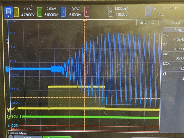
The test program streams a table of 192 L/R samples of a 4kHz sine wave of increasing amplitude. After all 192 L/R samples are transferred to the TAS2555, the I2S is turned off. The first sample of the table is a zero value, but after that, the table values immediately begin generate the 4kHz sine wave of increasing magnitude.

I should also mention that I have placed a 100mS delay between the Amp Init() call (ROM MODE 1) and the DMA/I2S init to ensure that the Amp should be ready for input (see code below).

Amp_I2CInit();    //ROM MODE 1

DelayMsWatchdog(100, WDT_MAIN);

DMA_AMP_Init();

Cy_DMA_Channel_Enable(DMA_AMP_HW, DMA_AMP_DW_CHANNEL);
I2S_AMP_Start();

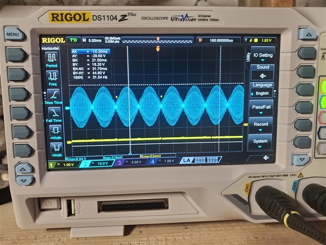
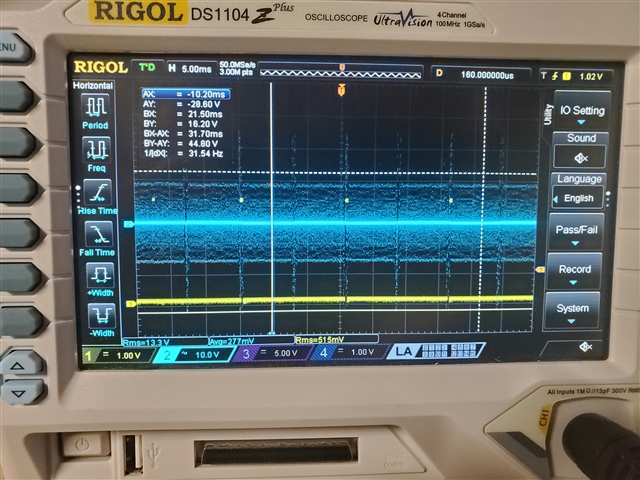
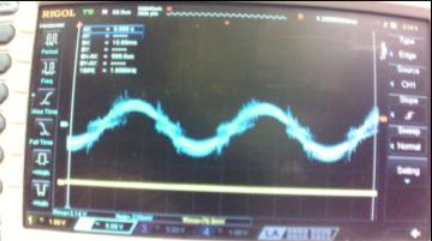
In the scope trace below, the YELLOW TRACE shows the I2S WCLK and the BLUE TRACE shows the TAS2555 audio output. 

I have two questions:

1) I would expect to see the amp's audio output respond essentially "in sync" with the I2S input. However, the audio output appears to be significantly delayed (relative to the I2S stream) by about 1mS.  Can you explain that delay?

2) After the I2S value stream comes to an end, I would expect to see a DC audio signal because no new I2S values are being transmitted into the amp. Instead, the amp's audio output appears to continue driving a segment of the 4kHz signal forever? Can you explain that?

Thanks,

Rich

  • Hi Rich,

    Can you please share the register configuration you're using for TAS2555?

    Best regards,
    -Ivan Salazar
    Applications Engineer

  • void Amp_I2CInit()
    {
        // Page 0
        Amp2555_i2cRegWrite(0x00, 0x00);
        // Book 0
        Amp2555_i2cRegWrite(0x7f, 0x00);
        // Software reset
        Amp2555_i2cRegWrite(0x01, 0x01);
        // use delay >= 100us
        BlockingDelayMs(0x01);
        // Mute / Powerdown / Reset ends
        // PLL begins
        Amp2555_i2cRegWrite(0x00, 0x00);
        Amp2555_i2cRegWrite(0x7f, 0x00);
        Amp2555_i2cRegWrite(0x00, 0x01);
        Amp2555_i2cRegWrite(0x73, 0x0f);
        Amp2555_i2cRegWrite(0x74, 0x0d);
        Amp2555_i2cRegWrite(0x00, 0x00);
        Amp2555_i2cRegWrite(0x7f, 0x64);
        Amp2555_i2cRegWrite(0x1b, 0x01);
        Amp2555_i2cRegWrite(0x1c, 0x07);
        Amp2555_i2cRegWrite(0x1d, 0x00);
        Amp2555_i2cRegWrite(0x1e, 0x00);
        Amp2555_i2cRegWrite(0x20, 0x07);
        Amp2555_i2cRegWrite(0x22, 0x08);
        Amp2555_i2cRegWrite(0x02, 0x10);
        Amp2555_i2cRegWrite(0x21, 0x04);
        Amp2555_i2cRegWrite(0x01, 0x08);
        Amp2555_i2cRegWrite(0x2b, 0x00);
        Amp2555_i2cRegWrite(0x2c, 0x20);
        Amp2555_i2cRegWrite(0x1f, 0x20);
        Amp2555_i2cRegWrite(0x2a, 0x40);
        // PLL ends
        Amp2555_i2cRegWrite(0x00, 0x00);
        Amp2555_i2cRegWrite(0x7f, 0x00);
        Amp2555_i2cRegWrite(0x22, 0x02);
        // Power up 1
        // Page 0
        Amp2555_i2cRegWrite(0x00, 0x00);
        // Book 0
        Amp2555_i2cRegWrite(0x7f, 0x00);
        // DSP,PLL, Ndiv , MDAC, MADC  power up
        Amp2555_i2cRegWrite(0x04, 0xf8);
        // Power up 3
        // Page 0
        Amp2555_i2cRegWrite(0x00, 0x00);
        // Book 0
        Amp2555_i2cRegWrite(0x7f, 0x00);
        // LASSD ,Boost power up
        Amp2555_i2cRegWrite(0x05, 0xa0);
        // LASSD ,Boost Vsense and Isense power up
        Amp2555_i2cRegWrite(0x05, 0xa3);
        Amp2555_i2cRegWrite(TAS2555_REG__SPEAKER_CONTROL, 0x3c); /*minimum gain*/
        // Unmute Begins
        // Delay
        BlockingDelayMs(0x01);
        // Page 0
        Amp2555_i2cRegWrite(0x00, 0x00);
        // Book 0
        Amp2555_i2cRegWrite(0x7f, 0x00);
        // CLASSD, Isense unmuted
        Amp2555_i2cRegWrite(0x07, 0x00);
        // Book 100
        Amp2555_i2cRegWrite(0x7f, 0x64);
        // classD soft unmute
        Amp2555_i2cRegWrite(0x07, 0x00);
        // Unmute Ends
    }
  • Hi Rich,

    Thanks for sharing the init script. I just noticed this is same application as this thread: https://e2e.ti.com/support/audio-group/audio/f/audio-forum/1192205/tas2555-tas2555evm

    I assume you're testing this now on the correct layout boards, correct?

    I'll double check what is the expected group delay with a default ROM configuration. Then I'll try with this reduced init script.

    That behavior of the device keep playing some samples of the latest received data seems like a problem derived from losing the clocks while playing. Have you tested by stopping the audio input data before stopping the clocks? I assume the output will be silent after you stop the clocks in that case.

    Best regards,
    -Ivan Salazar
    Applications Engineer

  • I think I understand your question correctly. The answer is that I already observed the Amps behavior in a number of different ways. 

    The I2S/DMA data buffer holds one complete 360 degree waveform. The first element of the data buffer is on an audio zero crossing (0 degrees) and the last element of the data buffer is also on an audio zero crossing (360 degree). The intention is to  repeat the buffer continuously. But to also keep the I2S data in phase synchronization with the Amp's audio output - so that the I2S zero crossings coincide with the audio zero crossings as closely as possible.

    I had initially observed the audio phase delay when the application was running in a continuous and uninterrupted state - no breakpoints. The audio output wave appears accurate forever (but with the unwanted phase delay).  

    I trying to debug the problem, I added breakpoints, and found that when the PSoC6 MCU was halted, the DMA and I2S hardware on the MCU would continue to run - corrupting the state of the data buffers. So I needed to restructure the code to periodically pause and restart the I2S and DMA clocks so that I had a place where I could safely place a breakpoint.

    So, perhaps, the repeating data can be solved by stopping the amp clocking at the same time that I stop the I2S and DMA clocks? If so, what is the correct way to do that?

    And, I think you are on the right track for looking at the ROM MODE 1 "group delays" for correcting the phase delay that I am observing on the audio output.

    Thanks,

  • Hi Rich,

    Thanks for the additional details.

    I tested TAS2555 on the EVM, using PPC3 ROM mode configuration as well as the reduced script I provided on the other e2e thread. Both have the same group delay. This is ~791.7us, which is about 38 samples for 48kHz sampling rate. This is most likely directly derived from the interpolation filter. You may test by adding the correspondent delay in your initial playback in order to align the I2S to the analog output.

    Best regards,
    -Ivan Salazar
    Applications Engineer

  • In other words, are you suggesting I could prefill 38 samples of dummy zeros and then begin sending the real waveform data?

  • Hi Rich,

    Yes, that could be a workaround for the group delay.

    Best regards,
    -Ivan Salazar
    Applications Engineer

  • Hello Ivan,

    I still expect to revisit the group delay issue in the near future. But, at the moment, I have a new question for you...

    I have noticed some unexpected behavior when changing the setting of the "current limit" register (0-0-0x2b). I am using this configuration:

        // Page 0
        Amp_i2cRegWrite(0x00, 0x00);
        // Book 0
        Amp_i2cRegWrite(0x7f, 0x00);
        // Software reset
        Amp_i2cRegWrite(0x01, 0x01);
        // use delay >= 100us
        BlockingDelayMs(0x01);
        // Mute / Powerdown / Reset ends
        // PLL begins
        Amp_i2cRegWrite(0x00, 0x00);
        Amp_i2cRegWrite(0x7f, 0x00);
        Amp_i2cRegWrite(0x00, 0x01);
        Amp_i2cRegWrite(0x73, 0x0f);
        Amp_i2cRegWrite(0x74, 0x0d);
        Amp_i2cRegWrite(0x00, 0x00);
        Amp_i2cRegWrite(0x7f, 0x64);
        Amp_i2cRegWrite(0x1b, 0x01);
        Amp_i2cRegWrite(0x1c, 0x07);
        Amp_i2cRegWrite(0x1d, 0x00);
        Amp_i2cRegWrite(0x1e, 0x00);
        Amp_i2cRegWrite(0x20, 0x07);
        Amp_i2cRegWrite(0x22, 0x08);
        Amp_i2cRegWrite(0x02, 0x10);
        Amp_i2cRegWrite(0x21, 0x04);
        Amp_i2cRegWrite(0x01, 0x08);
        Amp_i2cRegWrite(0x2b, 0x00);
        Amp_i2cRegWrite(0x2c, 0x20);
        Amp_i2cRegWrite(0x1f, 0x20);
        Amp_i2cRegWrite(0x2a, 0x40);
        // PLL ends
        Amp_i2cRegWrite(0x00, 0x00);
        Amp_i2cRegWrite(0x7f, 0x00);
        Amp_i2cRegWrite(0x22, 0x02);
        // Power up 1
        // Page 0
        Amp_i2cRegWrite(0x00, 0x00);
        // Book 0
        Amp_i2cRegWrite(0x7f, 0x00);
        // DSP,PLL, Ndiv , MDAC, MADC  power up
        Amp_i2cRegWrite(0x04, 0xf8);
        // Power up 3
        // Page 0
        Amp_i2cRegWrite(0x00, 0x00);
        // Book 0
        Amp_i2cRegWrite(0x7f, 0x00);
        // LASSD ,Boost power up
        Amp_i2cRegWrite(0x05, 0xa0);
        // LASSD ,Boost Vsense and Isense power up
        Amp_i2cRegWrite(0x05, 0xa3);
        Amp_i2cRegWrite(TAS2555_REG__SPEAKER_CONTROL, 0x54); /*minimum gain*/
        // Unmute Begins
        // Delay
        BlockingDelayMs(0x01);
        // Page 0
        Amp_i2cRegWrite(0x00, 0x00);
        // Book 0
        Amp_i2cRegWrite(0x7f, 0x00);
        // CLASSD, Isense unmuted
        Amp_i2cRegWrite(0x07, 0x00);
        // Book 100
        Amp_i2cRegWrite(0x7f, 0x64);
        // classD soft unmute
        Amp_i2cRegWrite(0x07, 0x00);
        // Unmute Ends
    Notice the line "Amp_i2cRegWrite(0x2b0x00);" which sets the BOOST_ILIMIT to 1.5A - this configuration works correctly and results in the desired waveform as shown below:
    Now, if I try to change the current command line to "Amp_i2cRegWrite(0x2b0x03);" which sets the BOOST_ILIMIT to 3.0A - this configuration does not enter into a stable waveform at all as shown below:
    between these two tests nothing else changes except that single line of code (same prototype, same test load and wiring, same probe wires, same power, and no other code changes). I have also, switched back an forth 3 times between 0x00 and 0x03 to confirm that the results above are repeatable.
    Do you have any thoughts on why simple increasing the BOOST_ILIMIT could cause the amplifier to stop producing a proper waveform (even with the same test load)?
    Thank you,
    Rich
  • Hi Rich,

    This may just be a problem on when the command is being executed. Please note that the command for 0x2b is actually part of the PLL configuration, which is book 0x64 page 0x00, while the current limiter configuration is located in book 0x00 page 0x00.

    Please try by adding your command 'Amp_i2cRegWrite(0x2b0x00);' somewhere after the PLL config ends, and make sure you're in book 0 page 0 by previous writes into registers 0x00 and 0x7F.

    Best regards,
    -Ivan Salazar
    Applications Engineer

  • Hello Ivan,

    Thank you for uncovering my mistake of changing the register in the wrong book.

    WeUpload  have a new issue. We are seeing increased amp noise at lower waveform amplitudes (eg near the zero crossings). This noise does not exist at higher amplitudes Can you look at the pictures below and suggest what you think is going on. 

    The waveform I2S is a simple sinusoidal.

  • Hi Rich,

    I'll check what could be the source of this noise and share further comments early next week.

    Best regards,
    -Ivan Salazar
    Applications Engineer