This thread has been locked.

If you have a related question, please click the "Ask a related question" button in the top right corner. The newly created question will be automatically linked to this question.

TLV320AIC3104: TLV320AIC3104 and TPA2012D2 connection and signals

Part Number: TLV320AIC3104
Other Parts Discussed in Thread: TPA2012D2

Hello,
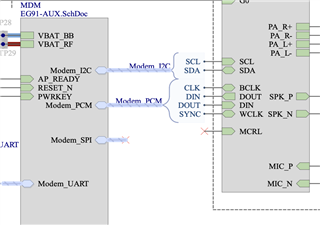
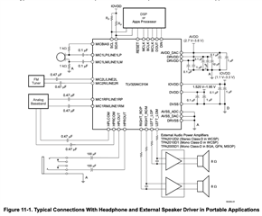
I have developed a cellular device, and I need help to solve the handsfree volume level. The circuit consists of a Quectel EG91 module, a TLV320AIC3104 IC and a TPA2012D2 interconnected as follows:

where the audio block is,

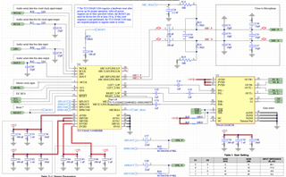
* the RESET pin (31) has been corrected

* R43 and R44 are not fitted 

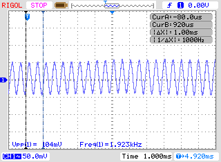
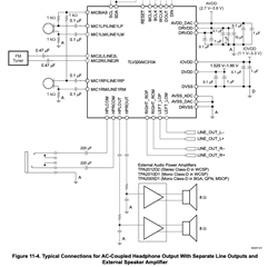
The CODEC headphone outputs work correctly, and you hear at the proper volume. It turns out that I am unable to measure the RMS voltages on the TLV320AIC3104 outputs, so that I can compare them to the specs. As I understand, and as expected, is that through the lines of pins 27, 28, 29 and 30 I can observe values like the following: 

I am able to measure on scope a signal in the order of 50mVpp which coincides with the frequency of the tone I am trying to reproduce. 

I assume that the power amplifier (TPA2012D2) works well, since if a signal of approximately 500mVpp is injected in the inputs pins 16, 17, 19 and 20; the speakers reproduces the sound with the expected volume. 

I have made modifications on the board to bring the circuit to the recommended ones:

and 

But I still don't have more amplitude in the signals, and therefore volume. 

The speaker selected is https://www.cuidevices.com/product/resource/cms-160925-078x-67.pdf 

I appreciate the help in advance

Greetings,

  • Hi Juan,

    Have you tried adjusting either the gain of the TPA2012 (G0 and G1 pins) or the DAC volume of the codec using I2C?

    Best regards,
    Jeff McPherson

  • Hi Jeff,  

    Yes, I have adjusted the gain of the TPA2012, and I can differentiate that it changes. I can more or less distinguish the noise floor. That's why I assume that the TPA stage is working correctly. 

    Also, I read 0x00 from the registers 43 and 44 (DAC's Left&Right volume control) on TLV320AIC3104. This means that the gain is at 0dB and that the channel is not muted.

    I understand that the Quectel EG91 modem performs all the necessary configuration to handle the codec. It even has AT commands to control the codec volume, which I have set to maximum. 

    I suspect the problem lies in the output audio level of the codec, which I can't measure well with the oscilloscope. I only get a sinusoid at the frequency of the desired tone with an amplitude of about 50mVpp. But this is just my intuition. I don't master the configuration of the TLV320AIC3104 and I guess the modem takes care of it.

    Thanks, 

    Best regards! 

    Juan 

  • Hi Juan,

    I see. Unfortunately I'm not familiar with the Quectel EG91.

    50mVpp is awfully soft since the full scale output should be closer to 4Vpp. Are you sending a full scale digital signal to the codec?

    You'll probably need to make some manual adjustments to the registers to get the right volume. Since the DAC volume is maxed, there's also Register 86 and 93 which increase the Line Output levels. You may also need to increase the gain of the amp depending on how loud of a signal you're driving into the codec.

    I also want to point out that 9.3.3 in the TPA2012 datasheet recommends using a lowpass filter on the output of the DAC to prevent out of band noise from being amplified by the amp. I don't think that directly solves the volume problem, but it could come up once you get it working.

    Best regards,
    Jeff McPherson

  • Hi Jeff, 

    I agree that the value of 50mVpp is very small. The digital signal is sent by the modem, and I would believe that it does it properly. But I don't know. I'm going to continue reading the codec data sheet. 

    I did the next: 

    - 1) Once the modem has initialize the codec, 

    - 2) Configure the registers that you recommended me: 86=0x99 and 93=0x99

    - 3) Then, I read all register from page 0. The values are in the attached PDF file. I marked in blue the configuration that I did after the modem initialize the codec. 

    TLV320AIC3104 registers configuration.pdf

    You can see the value of the registers 86 and 93, which are the ones you recommended to me.

    I don't notice any change in the sound level. Keeps as if I hadn't done anything!

    About the low pass filter, yes, I think the same as you.

    I'll back as soon as I have more results ..

    Thank you very much,

    Greetings!

  • Hi Juan,

    It looks like you're new settings muted the Line Outputs to the amp. Was that intentional? Also what do the orange lines mean?

    Thanks,
    Jeff McPherson

  • Hi Jeff, 

    I don't know why the line output is set in mute mode. I suppose the modem performs this configuration. 

    The orange lines are registers than had been modified by the modem and I marked to control them. Only that. 

    After modem did all codec configuration, I set other configuration and now I can heard a handsfree speaker level, without changes on the hardware. So the new setting are: 

    // set 0gB gain on HPROUT / HPLOUT and disconnect them from the outputs
    eg9x_send_cmd( 500, "OK", "AT+QIIC=0,0x18,0x%02X,1,0x%02X", 51, 0x04 );	// HPLOUT is high-impedance when powered down, HPLOUT is not fully powered up
    eg9x_send_cmd( 500, "OK", "AT+QIIC=0,0x18,0x%02X,1,0x%02X", 65, 0x04 );	// HPROUT is high-impedance when powered down, HPROUT is not fully powered up
    eg9x_send_cmd( 500, "OK", "AT+QIIC=0,0x18,0x%02X,1,0x%02X", 58, 0x04 );	// HPLCOM is high-impedance when powered down, HPLCOM is not fully powered up
    eg9x_send_cmd( 500, "OK", "AT+QIIC=0,0x18,0x%02X,1,0x%02X", 72, 0x04 );	// HPRCOM is high-impedance when powered down, HPRCOM is not fully powered up
    
    // set DAC_L1 is routed to LEFT_LOP/M and DAC_R1 is routed to RIGHT_LOP/M
    eg9x_send_cmd( 500, "OK", "AT+QIIC=0,0x18,0x%02X,1,0x%02X", 82, 0x80 );	// DAC_L1 is routed to LEFT_LOP/M, 0dB attenuation 
    eg9x_send_cmd( 500, "OK", "AT+QIIC=0,0x18,0x%02X,1,0x%02X", 92, 0x80 );	// DAC_R1 is routed to RIGHT_LOP/M, 0dB attenuation 
    
    // set 9dB gain on lines out and max gain eg9x_send_cmd( 500, "OK", "AT+QIIC=0,0x18,0x%02X,1,0x%02X", 86, 0x99 ); // Output level control = 9 dB, LEFT_LOP/M is not muted, LEFT_LOP/M is fully powered up eg9x_send_cmd( 500, "OK", "AT+QIIC=0,0x18,0x%02X,1,0x%02X", 93, 0x99 ); // Output level control = 9 dB, RIGHT_LOP/M is not muted, RIGHT_LOP/M is fully powered up

    Register number is in blue color, and value in orange color.

    To summarize, it seems that the modem performs some configuration on the codec, which is not suitable for the hardware that was designed. With this we have solve this issue. Now, I'm checking the microphone, since I don't have a voice when I make a call.It's probably also just configuration, or at least that's what I hope.

    Thank you very much for the help Jeff!!

  • Hello again!

    As I commented in my previous comment, the output audio is fixed.

    Now I'm trying to get the microphone to work. The circuit is the one shown in the first images. When I make a phone call, you can hear well what is said from the phone, but you do not hear what is said from the device in question. 

    The configuration I have made in the codec is as follows (Last 2 parameters are register and value): 

    // MIC configuration : 1: MIC1RP/LINE1RP and MIC1RM/LINE1RM are configured in fully differential mode.
    	// 1: Right-ADC channel is powered up.
    	// 00: Right-ADC PGA soft-stepping at once per sample period
    	eg9x_send_cmd( 500, "OK", "AT+QIIC=0,0x18,0x%02X,1,0x%02X", 12, 0x50 );			// Left-ADC high-pass filter –3-dB frequency = 0.0045 × ADC fS. Right-ADC high-pass filter –3-dB frequency = 0.0045 × ADC fS.
    	eg9x_send_cmd( 500, "OK", "AT+QIIC=0,0x18,0x%02X,1,0x%02X", 15, 0b01110111 );	// The left ADC PGA is not muted. Gain 59.5dB
    	eg9x_send_cmd( 500, "OK", "AT+QIIC=0,0x18,0x%02X,1,0x%02X", 16, 0b01110111 );	// The right ADC PGA is not muted. Gain 59.5dB
    	eg9x_send_cmd( 500, "OK", "AT+QIIC=0,0x18,0x%02X,1,0x%02X", 19, 0b11111100 );	// MIC1LP/LINE1LP and MIC1LM/LINE1LM are configured in fully differential mode. Left-ADC channel is powered up.
    	eg9x_send_cmd( 500, "OK", "AT+QIIC=0,0x18,0x%02X,1,0x%02X", 21, 0x80 );			// MIC1RP/LINE1RP and MIC1RM/LINE1RM are configured in fully differential mode. Input level control gain = 0 dB.
    	eg9x_send_cmd( 500, "OK", "AT+QIIC=0,0x18,0x%02X,1,0x%02X", 22, 0b10000100 );	// MIC1RP/LINE1RP and MIC1RM/LINE1RM are configured in fully differential mode. Right-ADC channel is powered up.
    	eg9x_send_cmd( 500, "OK", "AT+QIIC=0,0x18,0x%02X,1,0x%02X", 24, 0b11111000 );	// MIC1LP/LINE1LP and MIC1LM/LINE1LM are configured in fully differential mode. LINE1L is not connected to the right-ADC PGA
    
    	eg9x_send_cmd( 500, "OK", "AT+QIIC=0,0x18,0x%02X,1,0x%02X", 25, 0xC0 );			// MICBIAS output is powered to Vcc (3,3V)

    I can't find what the cause may be. If I whistle, I can observe the following over C27 and C28 using the oscilloscope: 

    Can you help me with this, please.

    Greetings!

  • Hi Juan,

    Looks like the inputs aren't connected to the ADC PGA even though the signal chain is powered up. See bits D6-D3. Double check register 19 and its related registers for similar errors.

    Best regards,
    Jeff McPherson

  • Hi Jeff, 

    While I review this, I have a doubt. The microphone is connected to the inputs on the right. Is it also necessary to connect the left-hand inputs to the ADC?

    I interpret that it would be ok to connect the right-line inputs to both ADCs, and configure the PGAs in the same way. In this way, have both channels with the input sound, which only comes from the right-channel. Is this correct?

  • Hi Juan,

    Yes you can connect a single given input to both left and right ADC paths to create a copy on two channels.

    Best regards,
    Jeff McPherson