TAS5720M: TAS5720m SAIF clock error with high FAULTZ all time

Part Number: TAS5720M

Tool/software:

I am trying to generate a tone on an 8-ohm speaker using ESP32 with I2S. Working conditions:

  • SAIF: I²S
  • 16-Bit Data, I2S_SLOT_BIT_WIDTH_32BIT
  • RCLK = 48 kHz
  • BCLK = 3.072 MHz
  • MCLK = BCLK

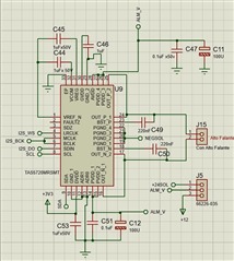
But I was not able to get any audio and the fault register always returns bit 3 as active. The faultz pin is always high. However, I didn't find anything in the datasheet that could help. Does anyone have any idea what might be happening? Here is the I2S configuration.

#define I2S_STD_MSB_SLOT_TAS_CONFIG(bits_per_sample, mono_or_stereo) \
    {                                                                \
        .data_bit_width = bits_per_sample,                           \
        .slot_bit_width = I2S_SLOT_BIT_WIDTH_32BIT,                  \
        .slot_mode = mono_or_stereo,                                 \
        .slot_mask = I2S_STD_SLOT_BOTH,                              \
        .ws_width = bits_per_sample * 2,                             \
        .ws_pol = false,                                             \
        .bit_shift = false,                                          \
        .left_align = true,                                          \
        .big_endian = false,                                         \
        .bit_order_lsb = false                                       \
    }
and configuration of tas5720 i2c 
    TAS5720_init(&tas, I2C_NUM_0, I2C_DEVICE_ADDR, true);
    TAS5720_mute(&tas, true);
    TAS5720_setSerialAudioInterfaceFormat(&tas, SAI_I2S);
    TAS5720_setChannelSelection(&tas, RIGHT);
    TAS5720_setAnalogGain(&tas, GAIN_25_DBV);
    TAS5720_setDigitalBoost(&tas, DIGITAL_BOOST_6DB);
    TAS5720_setVolume(&tas, 255, 255);
    TAS5720_mute(&tas, false);

    TAS5720_setShutdown(&tas, true);
    TAS5720_setPWMRate(&tas, RATE_16_LRCK);
  • Hi airton,

    It looks like the code you shared is specific to a driver you are using. Please read back the registers shown in table 9, I2C Register Map Summary, in the datasheet. This will help us debug your setup. Thanks.

    Regards,

    Sam

  • The ADDR being read is 8 from the table 9, and the bit that is coming high is 3 (CLKE).

    The library I am using is the following: github.com/.../TAS5720-Arduino

  • All the regs from table 9 read with a variable uint8_t

    I (10579) TAS5720: Reading from register 0x00 with data 0x01
    E (10579) TAG INFO: ADDR 0 : 1
    I (10589) TAS5720: Reading from register 0x01 with data 0xFC
    E (10589) TAG INFO: ADDR 1 : 252
    I (10599) TAS5720: Reading from register 0x02 with data 0x14
    E (10599) TAG INFO: ADDR 2 : 20
    I (10609) TAS5720: Reading from register 0x03 with data 0x80
    E (10609) TAG INFO: ADDR 3 : 128
    I (10619) TAS5720: Reading from register 0x04 with data 0xFF
    E (10619) TAG INFO: ADDR 4 : 255
    I (10629) TAS5720: Reading from register 0x06 with data 0x59
    E (10629) TAG INFO: ADDR 6 : 89
    I (10639) TAS5720: Reading from register 0x08 with data 0x08
    E (10639) TAG INFO: ADDR 8 : 8
    I (10649) TAS5720: Reading from register 0x10 with data 0xFF
    E (10649) TAG INFO: ADDR 10 : 255
    I (10659) TAS5720: Reading from register 0x11 with data 0xFC
    E (10659) TAG INFO: ADDR 11 : 252

  • Hi airton,

    1. According to table 12, you are entering shutdown mode, is this what you want?

    2. According to table 14, currently you are setting bit 4 to be 1. If you are writing to this register they should be set to 0. Thanks.

    Regards,

    Sam

  • I made some changes and got the following results:

    I (10392) TAS5720: Reading from register 0x00 with data 0x01
    E (10392) TAG INFO: ADDR 0 : 1
    I (10402) TAS5720: Reading from register 0x01 with data 0x00
    E (10402) TAG INFO: ADDR 1 : 0
    I (10412) TAS5720: Reading from register 0x02 with data 0x04
    E (10412) TAG INFO: ADDR 2 : 4
    I (10422) TAS5720: Reading from register 0x03 with data 0x80
    E (10422) TAG INFO: ADDR 3 : 128
    I (10432) TAS5720: Reading from register 0x04 with data 0xCF
    E (10432) TAG INFO: ADDR 4 : 207
    I (10442) TAS5720: Reading from register 0x06 with data 0x55
    E (10442) TAG INFO: ADDR 6 : 85
    I (10452) TAS5720: Reading from register 0x08 with data 0x08
    E (10452) TAG INFO: ADDR 8 : 8
    I (10462) TAS5720: Reading from register 0x10 with data 0xFF
    E (10462) TAG INFO: ADDR 10 : 255
    I (10472) TAS5720: Reading from register 0x11 with data 0xFC
    E (10472) TAG INFO: ADDR 11 : 252

    I set the shutdown bit to true, and the system itself entered shutdown mode automatically

  • Hi airton,

    I believe we have a miscommunication. Why did you set register 0x01 with data 0x00?  Please try setting it to 0xFD.

    Regards,

    Sam

  • Hi Sam, 

    I didn't change this register; it became zero on its own. I wrote the value 0xFD to it. However, the error persists. Here are the registers:

    I (10369) TAS5720: Reading from register 0x00 with data 0x01
    E (10369) TAG INFO: ADDR 0 : 1
    I (10379) TAS5720: Reading from register 0x01 with data 0xFD
    E (10379) TAG INFO: ADDR 1 : 253
    I (10389) TAS5720: Reading from register 0x02 with data 0x04
    E (10389) TAG INFO: ADDR 2 : 4
    I (10399) TAS5720: Reading from register 0x03 with data 0x80
    E (10399) TAG INFO: ADDR 3 : 128
    I (10409) TAS5720: Reading from register 0x04 with data 0xCF
    E (10409) TAG INFO: ADDR 4 : 207
    I (10419) TAS5720: Reading from register 0x06 with data 0x55
    E (10419) TAG INFO: ADDR 6 : 85
    I (10429) TAS5720: Reading from register 0x08 with data 0x08
    E (10429) TAG INFO: ADDR 8 : 8
    I (10439) TAS5720: Reading from register 0x10 with data 0xFF
    E (10439) TAG INFO: ADDR 10 : 255
    I (10449) TAS5720: Reading from register 0x11 with data 0xFC
    E (10449) TAG INFO: ADDR 11 : 252

  • Hi airton, 

    1. MCLK can be tied directly to BCLK, can you please double check whether the BCLK to RCLK ratio is constantly 64 and LRCLK is always 48kHz?

    2. Please check if the /FAULTZ pin has a pull up resistor to the DVDD pin.

    3. Does the /FAULTZ pin ever get pulled low? If a SAIF clock error occurs, TAS5720M will go into the sleep mode and the /FAULTZ pin becomes low.  During a SAIF clock error, the FAULTZ pin will be asserted low and the CLKE bit will be asserted high (register 0x08, bit 3). 

    Regards,

    Sam

  • Hi Sam, 

    1. R: The MCK and BCLK are tied together and have exactly the ratio of 64 constantly.

    2. R: Yes, the faultz pin has a pull-up resistor to the DVDD pin with a 100k resistor.

    3. R: At no time does the faultz pin go low.It always stays high all the time.

  • Hi airton,

    I will do some more research and get back to you shortly. In the meantime, can you try replacing the pull-up resistor on the FAULTZ pin with a 10k and let me know what changes. Please also forward the schematic. Thanks.

    Regards,

    Sam

  • I will make the change and get back with the results. Here is the schematic image of the TAS5720.

  • Hi airton,

    Sounds good. Currently in the schematic I do not see a pull-up resistor on the FAULTZ pin. What value is the ALM_V supply? Did you set the PWM frequency by writing to the PWM_RATE bits (bits 6-4, reg 0x06)?

    Regards,

    Sam

  • I had forgotten to add the pull-up in the schematic but implemented it on the board later. Currently, I am using 12V as the supply voltage. The PWM rate is set to 16 × LRCLK.

  • Hi airton,

    Please try pulling SCL and SDA high to 3.3V through a 2.5k resistor. Thanks.

    Regards,

    Sam

  • Currently there is already a 5V i2c pull up with a 560 ohm resistor. I2C is shared with other devices

  • Hi airton, 

    We recommend using an I2C pull-up of 2.4k to 3.3V. Why did you choose to VDD to be 5V and use a 560 ohm resistor? Thanks.

    Regards,

    Sam

  • I used 5V because other devices operate in this voltage range, and I believe that 560 ohms resulted in a high current. I will adjust it to 4.7k ohms and see if anything changes.

  • Hi airton,

    Please try to adjust the I2C and the FAULTZ pull-ups and let me know what you see. Thanks.

    Regards,

    Sam

  • The changes were made, 3.3V with 2.7k ohms for the I2C pull-up and a 10k ohm pull-up for the faultz pin. The faultz pin stayed high the whole time.

  • Hi airton,

    Can you send screenshots of the I2S output waveforms and the PWM signal? If you have the TAS5720MEVM can you try feeding the I2S signals to the EVM (short the MCLK and BCLK together) and report the status of the fault pin. Thank you.

    Regards,

    Sam