This thread has been locked.

If you have a related question, please click the "Ask a related question" button in the top right corner. The newly created question will be automatically linked to this question.

TPA3136D2: audio filtering

Part Number: TPA3136D2
Other Parts Discussed in Thread: TPA3001D1,

Hi,
I was able to send 12 dB audio through the headphones from the Colibri 3.2 eval board
as an input to the TPA3612D2EVM. I used a sound meter and the sound from the demo
is comparable to the sound from the existing application.
 
The remaining part is to figure out is the filter at the output of the power amp. Some distortion
in the audio is heard.
 
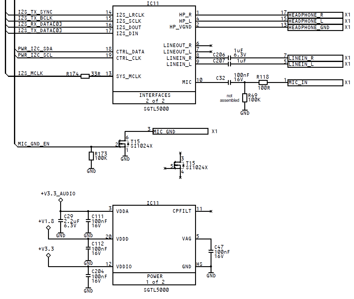
I have attached the audio interface schematic used in the existing application. I tried soldering the power
amp output directly to the low pass filter (disconnecting the old class D from the existing application).
This test did not work so well, some component smoked on the existing application board which means the
loudspeaker is possibly being overloaded.

The EVM and new class D design is powered by 12V. This puts the voltage at the PLIMIT at 5V. Given
a 4 Ohm 3W loudspeaker, should this voltage be reduced to 3.4 V to avoid speaker overloading?

 
Can the same LC filter be re-used at the output of the new class D part before entering the relay switches?

Is there benefit to viewing signals on the scope? I have a function generator I can use to send 0.2 V rms
to the power amp EVM directly and I can see this signal on the scope. What outputs from the EVM to I
connect to the scope to view output amplitude/and distortion?
 
Thanks,
Priya
 ICoreDigiAudio.pdf

  • Hi Priya,

    PLIMIT function can be used to limit the output power by seting the appropriate voltage on this pin. The limit can be thought of as a "virtual" voltage rail which is lower than the supply connected to PVCC. The "virtual" rail is approximately four times the voltage at the PLIMIT pin. Pleaes find more detailed info in section 9.3.3 in the TPA3136D2 datasheet. So for 4ohm/3W speaker, the maximum voltage is around 4.9V, then please set the voltage on PLIMIT pin to around 1.25V.

    I'm not sure whether you are talking about TPA3136D2 or TPA3001D1. Because the device in the title is TPA3136D2, but it't TPA3001D1 in the SCH. TPA3136D2 has fixed 26dB, so the output is supposed to be 4Vrms if the input is 0.2Vrms.

    For the LC output filter design, please refer to the following document and design tool.

    Best regards,

    Shawn Zheng

  • Old design TPA3001D1 with obsolete codec. Will the LC filter (at the output of TPA3001D1)

    from the old design work with TPA3136D2? I will read the documents you offered more closely.

    Thanks,

    Priya


  • Hi Priya,
    TPA3001D1 and TPA3136D2 both work in BD mode, I think the filter also works for TPA3136D2. For 4Ohm load, you could use larger capacitors in the LC filter for a better Q value.
    Best regards,
    Shawn Zheng
  • Shawn,
    How to determine the value of Rs in the PLIMIT equation (Section 9.3.3 of TPA3136D2 datasheet)?
    Can you explain some more how you determine "So for 4ohm/3W speaker, the maximum voltage is around 4.9V, then please set the voltage on PLIMIT pin to around 1.25V."

    Specifically which capacitor values do you recommend changing? One LC has values 15 uH/0.22uF and the next LC pair (ferrite bead it seems like) uses 220 Ohm 1 nF.

    Thank you,
    Best Regards,
    Priya
  • Shawn,
    One more question-- if voltage on the PLIMIT pin is 1.25 V, this changes the 39K resistor from
    Fig 19 of the TPA3136D2 datasheet to 6.5 kOhm. PVCCis 12V. Please confirm.
    Thanks,
    Priya
  • Shawn,
    Still waiting for your help.

    I set the voltage at the PLIMIT pin to 1.25V on the TPA3136D2EVM. The sound coming out of the analog headphone output has been set to 12dB (max possible from SGTL 5000 codec from the colibri 3.2 eval board).

    The loudspeaker (4 Ohm 3W) still makes some popping noises. I tried two different loudspeakers, they both do the same. The speaker plays the demo sound file for a while and then the sound just stops. When power is turned off and back on, the sound comes back.

    Any thoughts on this situation? It could be a test setup issue. Edited to add: I have no filter hooked up between the EVM output and loudspeaker. There are no switches or anything else in this demo set up.

    I appreciate your feedback on this. I have one more day to work on this project.

    Thanks,
    Priya

  • Hi Priya,
    For your 3W/4Ohm speaker, the max acceptable voltage on it is 4.9V, right? 4.9V*4.9V/(2*4ohm)=3W. Then PLIMIT voltage can be adapted to 1.25V to achieve a upclipped 4.9V output. If you can accept a 10% THD output, you could use even lower PLIMIT voltage. The two resistors on PLIMIT pin can be adapted to get an appropriate voltage on it.
    Did you try this on the TAP3136D2 EVM? I mean using both the device and the output filter on the EVM? Apply analog signal on the input and connect the speaker on the output of the EVM board. Can you see the same issue?
    For the pop noise, are you using single-ended input or differential input? Please make sure there is no other components between the DAC/Codec output and amp input(except 1uF input capacitor), e.g. LFP is not necessary. Make sure the matching between INN and INP is good enough. If you are using single-ended input mode and a wire is used between DAC/Codec board and amp board, the matching between INN and INP is bad and a pop noise is expected.
    Why do you use two serial LPF filter on the output? If inductor is already used, ferrite bead + capacitor filter is actually not necessary. Please also remove C190, which is unexcepted for BD mode.
    Best regards,
    Shawn Zheng
  • Shawn,
    Thank you for your reply. The factor of 2 in the denominator for the max acceptable voltage comes from Vpp to Vrms conversion, I was missing this. If not correct, let me know.

    Will a 100 KOhm resistor in series with the 1uF cap work to match the RINN and RINP? If not, how to match these two inputs?

    For the LC filter, I understand you want to retain L15, C185, L16 and C187 only. What value to you recommend for C185 and C187? Are the values for L15 and L16 OK?

    I am using voltage divider rule to determine the voltage between PLIMIT and GND, which you suggest as 1.25V. If this is incorrect, please let me know.

    I will try setting a filter at the output of the EVM today, if you can quickly suggest values for C185 and C187 that will be great.

    Best regards,
    Priya
  • IMX_AUDIO_INTERFACEFilter.pdf

    Adding updated TPA3136D2 schematic with LC filter. Please review and comment on values for R42, R3, R4, L1-C3, L2-C4.

    I will re-run demo with these values.

    Thank you,

    Best regards,

    Priya

  • Hi Priya,

    Sorry for the reply due to the time difference. For the updated SCH, there are some problems:

    1. Please place the snubber C1/R1 in paralleled with C144. The same is C2, R2 adn C145. you could find the ferrite bead in output filter application in the Figure18 in TPA3136D2 datasheet.

    2. Pin5 and Pin6 can be connected to GND, but pin3 and Pin4 can be left open. 

    3. There is some problem in the PLIMIT voltage divider circuit. the right end of R65 should be connected to GVDD.

    4. For the 100kOhm resistors in the input circuit, I think it's not necessary. Please remove all of the components between the output of DAC/Codec and the input of the amp, just reserve 1uF capacitors. 

    For the output filter design, please refer to the document and tool in below. I belileve you can design the appropriate LC filter for your application very easily.    

    Best regards,

    Shawn Zheng

  • Hi Pyria,
    Please help to close this question if it's answered. Let us know if you have more question.
    Best regards,
    Shawn Zheng
  • Shawn,
    Thank you for your reply. I got back from time off today. It seems like there is a revised Fig 19 in the TPA3136D2 datasheet. It offers greater clarity on how to configure the EVM output for mono load as well. I will be looking more closely into this the next few days. Until then, I need this ticket to stay open.
    Best regards,
    Priya
  • IMX_AUDIO_INTERFACE.pdfShawn,

    I updates the schematic based on your feedback. (file attached). My question is, there does not seem

    an easy way to connect the TPA3136D2 EVM output in the PBTL output configuration (Fig 19 from the

    TPA3136D2 datasheet). I don't have a means of checking the sound quality for the chosen parameters

    if the EVM cannot be connected this way. Please advice.

    Thanks,

    Priya

  • I may have added an extra LC filter prior to the loudspeaker that I removed. I have attached the revised schematic for review. I am also looking Table 4 Setting 2 for the PBTL mode. If these settings are used, will the output from Fig 4 of the TPA3136D2 EVM schematic look more like Fig 19 of the TPA3136D2 datasheet? I have to set up the LC filter at the EVM output.

    Thanks,

    Priya

    3107.IMX_AUDIO_INTERFACE.pdf

  • Hi Priya,

    Thanks for the update. I think there is no obvious issue in your SCH design.

    You could set the EVM board in PBTL mode according to the table 4 in the EVM user's guide. But it's a little different from the Figure 19 in the datasheet. The output is combined after inductors in the PBTL mode on EVM, while it's before inductors in Figure19. But the performance should be very similar.

    Best regards,

    Shawn Zheng 

  • Shawn,
    Thank you for your reply. I will go ahead and check the audio output using the ferrite bead filters on the EVM.
    (no external LC filter on the EVM output). I will post back if there are any audio quality issues.

    Best Regards,
    Priya
  • At this time, the schematic will be used as it is. There is trouble looking at the function generator sine wave on the oscilloscope (input to the EVM). When the boards come back, actual testing will happen with the chosen LC filter. If I have questions, I will open a new thread at that time.
    Thank you,
    Priya