This thread has been locked.

If you have a related question, please click the "Ask a related question" button in the top right corner. The newly created question will be automatically linked to this question.

LMK04828: Multi board synchronization

Part Number: LMK04828
Other Parts Discussed in Thread: LMK04832, LMK00301

Hey

I have a system that contains several boards with High Speed ADCs and DACs (base on Xilinx RFSoC), for each one of the boards the clock input to the ADCs and DACs reference clock is generated by LMK04828 device.

Since the LMK04828 device required dual - input crystal and local oscillator

I wanted to ask if there is a way the I can synchronize between my boards DAC/ADC reference clock using multiple LMK0482B’s

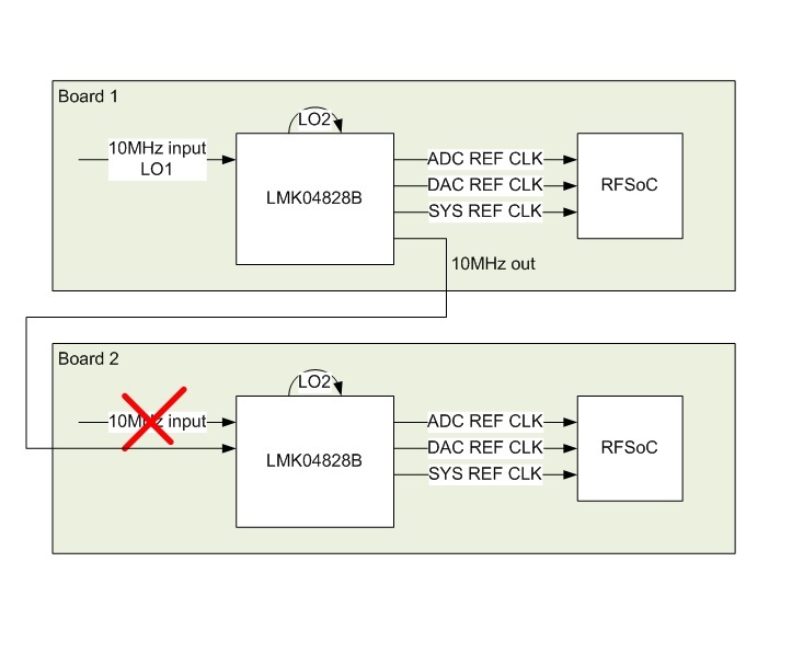
Please see illustration

My concern is LO2 that is different between the two boards

is there a way to do that?

BR

  • Hello Elhanan,

    It is possible to do multi-device synchronization.  Please take a look at this app note about multi-clock synchronization: www.ti.com/.../snaa294

    When you say synchronize, do you mean..

    • JESD204B synchronization where all clocking is deterministic? or
    • for the ADC/DAC clocks to also have a rising edge at the same moment in addition to JESD204B synchronization?

    Provided JESD204B synchronization is required, if the frequency of SYSREF is 10 MHz or otherwise n*10 MHz for n >= 1, you could do zero delay mode on the second device with the SYSREF divider.  Then when you request SYSREFs from the first or second device, the SYSREF would always occur on the same LMFC for JESD204B alignment.  This is the simplest approach.

    You may also provide both a reference clock and SYSREF clock to the downstream LMK04828 and re-clock the SYSREF generated from the first device.

    73,
    Timothy

  • Hey Timothy

    I need that the ADCs and DACs in all of the system Boards (all board have it own LMK04828) to have rising edge at the same moment "as if" it was one "big" board with one LMK04828.

    you said that 

    "You may also provide both a reference clock and SYSREF clock to the downstream LMK04828 and re-clock the SYSREF generated from the first device"

    Can you pleas illustrate it in some diagram with reference to the LMK04828 inputs and outputs that it gets? (maybe base on my)?

    thank you

    BR

  • Hello Elhanan,

    Could you advise your adc/dac/sysref frequency?  Is the SYSREF frequency flexible then?  Typically it is LMFC * n where in >= 1.

    73,
    Timothy

  • Hey Timothy

    My LMK04828 have the folowing:

    1. 10MHz TCXO in the CLK_in1 input

    2. 160M VCXO VX-501-0245-160M0

    3. My ADC and DAC frequency can be between 100MHz to 150MHz (using internal RFSoC PLL to upper it to 1GHz)

    4. My SYSREF is not determined yet so - yes, it's flexible

    Thank you

    Elhanan

  • Hello Elhanan,

    I'll send you an update on Monday.

    73,
    Timothy

  • Hello Elhanan,

    I expect by Thursday I should be able to update you on this topic.

    73,
    Timothy

  • Hello Elhanan,

    Thank-you for providing your frequency information.  You have quite low frequencies.  When your frequencies are so low single loop jitter cleaning may be able to get you the best performance.  In this case the output frequency will your VCXO frequency or an integer division of it.  So the dual loop may still give you some more flexibility.
      - You can use LMK04828 in single loop jitter cleaning mode using the external VCO input for PLL2.  Then provide your reference to OSCin.
      - Note, LMK04832 is an upgraded part from LMK04828, it is a bit more flexible here in that it allows single loop operation with a reference from OSCin or CLKinX.
        > The LMK04832 can produce 10 MHz from the clock output divider.  The LMK04828 max CLKout divider is limited to 32.
        > The LMK04832 PLL2 phase detector can operate at 160 MHz which will allow for better PLL2 performance given your 160 MHz VCXO.
        > The LMK04832 VCO frequency can achieve 3200 MHz, this frequency will also allow the 160 MHz phase detector to best be utilized... For example: 160 PDF --> 3200 MHz VCO --> /x = ADC/DAC reference freq; SYSREF divider = x * y.  If x = 25, then ADC/DAC frequency = 128 MHz.  Then SYSREF frequency could be 128 MHz / y.

    Here is a solution for you to consider which matches fairly closing to what you proposed.

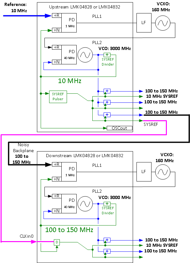
    The upstream LMK04828 device is configured straightforwardly to achieve your output clock frequencies and SYSREF frequency as desired.  The SYSREF pulser mode is used for JESD204B.   Another output with the same frequency as the ADC/DAC clock is used as a reference to a downstream LMK04828.  One deviation is that a frequency > 10 MHz is used as a reference to the downstream device because LMK04828 can't divide down to 10 MHz from internal VCOs on device clock (/32 max).  LMK04832 could use 10 MHz.

    The downstream LMK04828 is configured for nested zero delay mode using the SYSREF divider as the feedback source.  The SYSREF divider is configured to operate at the reference frequency.  More on why to use the SYSREF as feedback source below.  ZDM will allow the phase of the downstream LMK04828 output clocks to be deterministic with respect to the upstream LMK04828 ADC/DAC clocks.  The phase of these outputs may now be controlled by adjusting the digital delay on upstream LMK04828 output clock.  The step resolution will be the digital delay of the upstream device.  Assuming 3000 MHz VCO, this would be 0.5 / 3000 MHz = 166.67 ps/step.  The LMK04828 (not LMK04832) also has an analog delay on PLL1 R & PLL1 N which can be used on the downstream device to shift the input to output phase in ZDM.  It has a step of ~200 ps.  Used together with the digital delay step above, finer adjustments the difference of the two delays could be made.  Using the ADLY increases variation over temperature.

    The reason to use the SYSREF divider on the downstream device is it can also re-clock an input on CLKin0.  If the same clock is used for feedback to PLL1 and re-clocking the CLKin0, then there is a known timing relationship between the reference and the SYSREF/CLKin0 input for the purpose of re-clocking the SYSREF signal onto VCO phase domian of the downstream device and then on out to JESD204B targets of the downstream of the LMK04828.  Even though the SYSREF frequency is higher than is desired, it will only transition at the frequency of the CLKin0 input which is coming from the SYSREF output of the upstream LMK04828 device.
      - This re-clocking is really good when you have high frequency outputs... but because your frequencies are so low, you would be fine simply bypassing the CLKin0 signal straight to the output.  Analog (or even digital delays) could be used a the downstream SYSREF output.  Note, even if there is a shift in the SYSREF clock equal to a VCO period, that will not impact the JESD204B SYSREF timing as ~333 ps is time delta is much less than SYSREF valid window created by a say, 150 MHz device clock which has a period of ~6.6 ns.

    Hopefully between the app note and this diagram, you're able to visualize how you could do this multi-device synchronization.

    If you are concerned about the phase alignment between the device clocks given the delay adjustments described above, consider operating in a tree architecture where the upstream device now drive two downstream devices.  Each of these downstream devices will clock the ADC/DACs.  There will still be part to part skew variation.

    In this I've made the assumption that the connection between boards the signal may not be clean and the clock will require jitter cleaning given your original usage of dual loop jitter cleaners for the downstream board.  If the connection is clean you could consider a single LMK04828 with fan-out to the two boards.  Another performance improvement to consider is single loop jitter cleaning, since PLL2 actually adds jitter to provide the the flexiblity that a high frequency gives you in (a) being able to divide down to different frequencies and (b) allow fine timing resolution adjustments.

    Thank-you for your patience, sorry for the time it took me to respond in more detail to you.

    73,
    Timothy


  • Hey Timothy

    thank you for your design recommendation, however it might be a little bit hard for me to pass two clocks along my system cables (10MHz and SYSREF)

    so before I’m taking your full recommendation, I was wonder if we can downgrade the performance a bit, with the flowing suggested architecture:


    1. I have one master and 10 slaves (and they are identical PCB assemblies)
    2. The Master split the SYSREF with LMK00301 to the 10 slaves
    3. Each one of the slave gets the SYSREF from SY89544 de-mux (because each one of the slaves will get the SYSFER from different on board connector, so I have to use the De-Mux)
    4. Each one of the slaves have its own 160MHz VCXO and 10MHz TCXO.

    Can it work using the SYSFER only? What will be the downgrade in the performance not to transfer the 10MHz?

    Thank you

    Elhanan

  • Hello Elhanan,

    This configuration would not reduce your phase noise performance since the PLL1+VCXO is performing jitter cleaning.  As before, using an LMK04832 which supports 160 MHz PDF may help improve your performance or selecting a slightly lower/different VCXO frequency that is more optimum for your outputs.  Consider using the frequency planner in the LMK04832 TICS pro to assist.

    If you can have only the one signal to your downstream devices, then if you use the 10 MHz reference which is your SYSREF, you will be able to run 0-delay mode and align everything.  SYSREF divider and any dividers which produce frequencies related to 10 MHz.  Or GCD(10 MHz, other frequency) = 10 MHz.

    * However, with only a single clocking connection (10 MHz reference) to each downstream device the only way to cause a SYSREF to each converter element would be to request SYSREF by CMOS SYNC pin or software request.  At this time, I'm not sure the timing requirements for the software request (if possible), but if you provide a SYNC pulse on the reference falling edge, then you should receiving SYSREF from all devices at the same time.

    73,
    Timothy