This thread has been locked.

If you have a related question, please click the "Ask a related question" button in the top right corner. The newly created question will be automatically linked to this question.

LMX2571EVM: Power down and up from CE pin

Part Number: LMX2571EVM
Other Parts Discussed in Thread: LMX2571

Hi team,

My customer is evaluating LMX2571EVM.

About the powering down and  up from CE pin as described in DS 7.3.11, my customer tried FCAL_EN=1 but it didn't work.

The POWERDOWN bit based power cycle is working correctly.

Could you please advise how to set up after CE pin going high?

The test result is shown below. The values inside parenthesis are EVM current consumption.

TCXO is external 17.92MHz. LD LED is kept same.

The written data is as attached.

 LMX2571.tcs

①POWERDOWN bit test (succeeded)

 Verify RFOUT (50.3mA)

 0x001083 powered down (0.9mA)

 0x000083 powered up(50.3mA)
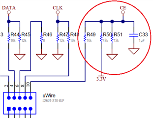
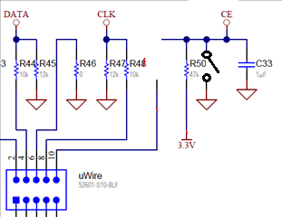
 

CE pin power down (failed)

 Verify RFOUT (50.3mA)

 CE=0 powered down(1mA)

 CE=1 current increases (38.4mA), but no RFOUT

 0x000083 further current increase, (52.6mA), but no RFOUT

 All register written, output verified(50.3mA)


③Register & CE pin power down test (reference)

 RFOUT verified (50.3mA)

 0x001083 power down(0.9mA)

 CE=0 keep power down (1mA)

 CE=1 Increases current (38.4mA), No RFOUT

 0x00083 Further increases current, (52.6mA) No RFOUT

 All registers are written then powered up (50.3mA)


Register & CE pin power down test (reference)

 RFOUT verified (50.3mA)

 CE=0 keep power down(1mA)

 CE=1 Increases current (38.4mA), No RFOUT

 0x001083 power down(0.9mA)

 0x000083 Further increases current (36.3mA), but no RFOUT

 All register written, further increases current (44.4mA), but no RFOUT

   After that, it needs to turn off and on the power supply to power up again.


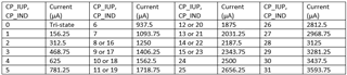
One more question, could you please provide table for relation between current and register values?

In TICS pro, it looks like like it duplicates from 1250uA - 2343.8uA.


Best regards,

Itoh

  • Hi Itoh-san,

    When the device comes out of the powered down state, either by resuming the POWERDOWN bit to zero or by pulling back CE pin HIGH (if it was powered down by CE pin), it is required that register R0 with FCAL_EN=1 be programmed again to re-calibrate the device. That is:

    1. CE pin power down

    - pull CE pin HIGH

    - program R0 (with FCAL_EN=1)

    2. POWERDOWN bit power down (MULT = 1)

    - program R0 (with POWERDOWN = 0 and FCAL_EN=1)

    2. POWERDOWN bit power down (MULT > 1)

    - program R0 (with POWERDOWN = 0 and FCAL_EN=0)

    - program R0 (with POWERDOWN = 0 and FCAL_EN=1)

    Full charge pump current setting as follows:

  • Hi Noel-san,

    As described in tested sequence #2, my customer tried to program R0 (FCAL_EN=1) after CE pin high (0x000083), but no RF output confirmed.

    Could you please double check the missing setting at this point?

    Regards,

    Itoh

  • Hi Itoh-san,

    We have verified toggling CE pin High/Low across temperatures before, we are confident that there is no locking issue.

    How do they connect the CE pin? If they have R49 = 10k and C33 = 1µF, the CE pin rise time will be very long, this might be an issue. Reduce R49 to 33Ω and change C33 to < 100pF or even remove it.

  • Hi Noel-san,

    On the customer's EVM, R50 and C33 are populated but R49 and R51 are DNP.

    They connect mechanical switch directly between CE pin and GND.

    They run the command 1 sec after the CE pin goes floating, so the CE pin voltage should not be the cause. 

    The test sequence is shown below.

    FYI, it works if Write All Registers.

    Please correct me if the below procedure is wrong.

    Test1

              CE pin and GND  goes floating by the switch

              After 1 sec, check the checkbox at User Controls display

              No RFOUT


     Test 2

              CE pin and GND  goes floating by the switch 

              After 1 sec, click Write Register button on right top of w Registers display

    (write 0x000083 to Data box

               No RF output

    Regards,

    Itoh

  • Hi Itoh-san,

    When the switch is closed, CE pin is shorted to ground, C33 is discharged.

    When the switch is opened, C33 will be slowly charged up through R50 because of the large RC constant. I worry that this slow rising edge may be causing the issue customer is seeing. Can the customer change the RC values to 33Ω and 100pF?

  • Hi Noel-san,

    Now it works! Thank you so much!

    Regards,

    Itoh