Other Parts Discussed in Thread: LMK61E2
Good Morning/Afternoon Texas Instrument Support.
Thanks for your time and support until now.
I have already read https://e2e.ti.com/support/clock-timing-group/clock-and-timing/f/clock-timing-forum/410251/lmk01801-sync-timing
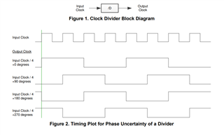
So I know that clock with frequency less than the original (diveded by 2 or more) there is a phase uncertainty unless the clock derive from the same divider

Here is the setting:
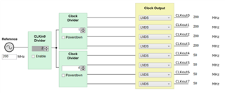
- uWire control and SYNC0=SYNC1
- Clkin0 and Clkin1 are both 200MHz and synchronized (they are derived from a programmable LMK61E2 through a Texas Instrument LVPECL or LVDS buffer CDCLVP2102RGTR or CDCLVD2102RGTT)


I expect that:
- LVDS Clokc BankA NOT DIVIDED CLKout0, CLKout1, CLKout2, CLKout3 are in phase with minimum intra skew 3ps (pag 10)
- LVDS Clokc BankA DIVIDED by 4 CLKout4, CLKout5, CLKout6, CLKout7 are in phase with minimum intra skew 3ps (pag 10), skew with the above
- Skew between LVDS Clokc BankA NOT DIVIDED and VDS Clokc BankA DIVIDED by 4 around 400ps (the value is true for 50 MHz https://e2e.ti.com/support/clock-timing-group/clock-and-timing/f/clock-timing-forum/859944/lmk01801-output-skew-between-different-divider , but i do not know if is true otherwise)
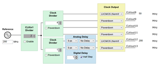
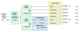
- CLKout8 CMOS will be in casual phase relationship with CLKout1, it will NOT have the same phase of Clokout4.
- CLKout12 CMOS will be in deterministic relationship (pahse 0) with CLKout0 because SYNC0=SYNC1 and same syncronized frequency for Clkin0 and Clkin1 (am I wrong?)
- I need an estimation of the skew between CLKout12 and CLKout0. If it is more than 250 ps I could not use this solution.
- I also need an estimation of CLKout8 to CLKout4 but the skew if far less stringent concern
Thanks for your time and best regards.


