This thread has been locked.
If you have a related question, please click the "Ask a related question" button in the top right corner. The newly created question will be automatically linked to this question.
Hello every one.
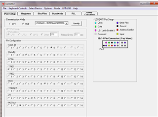
I have a LMX2492EVM board, a USB2ANY and use TICS PRO to control it.
everything is ok with CW mode, the PLL can lock and DLD is OK。
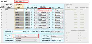
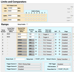
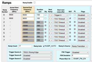
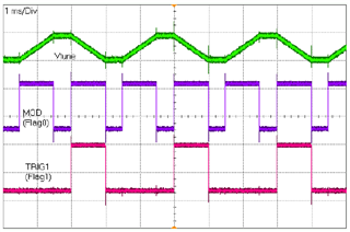
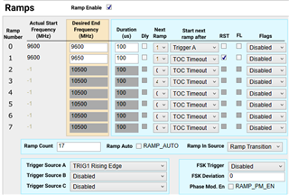
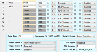
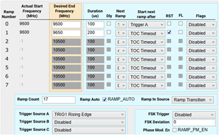
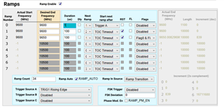
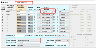
It seems also OK with Ramp mode when "Start next ramp afer" whith "TOC Timeout", I think they run with free mode.
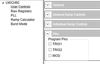
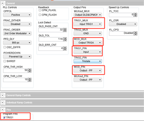
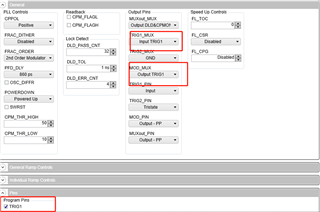
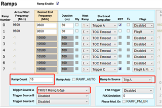
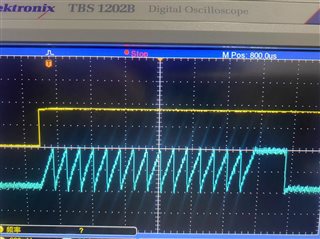
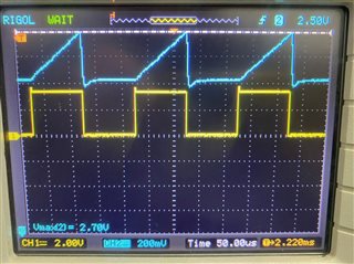
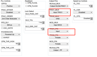
When I want to test trigger mod ,like use TRIG1_MUX PIN、 TRIG2_MUX PIN ,etc. to trigger LFMCW,but It is not work.
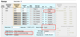
Also, I am according to the LMX2492EVM GUIDE.pdf section3.2.2 "Frequency Shift Keying (FSK) Example" to generate FSK , it is not wok too.
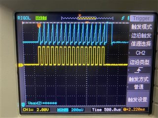
I thought the trigger signal is come from USB2ANY to uWire, but it seems no TTL tigger signal.
The firmware is 2.7.0.
In old userguid document, I see there are some signal allocation options in CodeLoader. but there is no similar options in TICS PRO, so I want to know how to comfirm the USB2ANY trigger signal is normal
thinks
the old CodeLoader.
Thanks for your reply.
Today I have a other test.
Set "TRIG1_MUX"="“input= TRIGER1” TRIG1_PIN=INPUT
Set "MOD_MUX"=OUTPUT TRIGA MOD_PIN=Output_PP
I use a oscilloscope to monitor at TP_TRIG1 (R66) , when I check and uncheck "Program Pins " "TRIG1",the oscilloscope shows the TTL up and down, it seems ok and this pin was controlled.
then, I set oscilloscope to monitor at TP_MOD (R71) --Ouput trigAand set RAMP caculator again , the simplest example :Continuous Sawtooth Ramp Example.
but when I check and uncheck "Program Pins " "TRIG1",the oscilloscope shows TP_MOD ---TriggerA is NO TTL signal, so there is no LFM signal generated.
I want to kwnow there is some thing wrong in my software setting?
thanks.
hello ,thanks for your reply. I think maybe I find the reason: the Triger_1 from USB2ANY uWire pin only change once when I check and uncheck "Program Pins " "TRIG1" , so there only one LFM signal at once. Due to the short time of waveform(only 100us and only once ),my spectrum analyzer and my eyes cannot capture them.
Today I use a function generator to generate a 3.3V TTL continuous square wave, then, the spectrum analyzer with "Trace MAX hold" can capture them.
So I wanna to ask a other question:
How to generate a frame LFM pulse (such as 128 or 256 LFM)by ONE trigger?
How to use and set "Rampcount" to get a frame? I set it as 128 but it seems not work.
thanks
I have search in this forums and find similar question LMX2492: how to use the LMX2492 ramp count function? - Clock & timing forum - Clock & timing - TI E2E support forums.
I try to follow that issue.
first I use this setting , but when a check and uncheck "Program Pins " "TRIG1" only one chirp come out.
then, I use other setting like this
the oscilloscope captured all the trigA/flg0/trigB signal
but there is only ONE LFM signal :by using spectrum analyzer monitor at 9625MHz SPAN=0Hz as time domain and trigger by Video ,only one signal after I check and uncheck "Program Pins " "TRIG1" , not 16 sequences
I think maybe something wrong with my TICS Pro setting ,not hardware fault.
could you help me?
thanks
Hi ,thanks your reply.
I tried this setting, Its seems the EVM can generate ramp count after one TTL trigger from trig1(TRIGA).
however, due to I check the "RAMP_AUTO", it seems " Automatically clear RAMP_EN when RAMP Count hits terminal count"(from datasheet pp25 Table 8). the next TTL trigger cannot repeatedly generate LFM frame again .so I need to manual check and uncheck “Ramp Enable” to generate next frame.
Should I need to use this sequential in my embeded code to repeatedly generate LFM frame ?
1) setting every registers about RF/RAMP/ trigger parameters
2) set RAMP_AUTO R84[5] register as 1 for enable Automatically clear
3) set RAMP_EN R58[8] as 1 for enable RAMP
4) give TTL trigger to LMX2492 to generat LFM chirp count sequnces.
5)use some flag signal to trigger ADC sampling
6)after all sampling , go to 3) set RAMP_EN R58[8] =1 again to next sequnces
Is it ok? or there is other simpler method?
thanks
I test it the scope like this below.
I think the Ramp 0 (CW 100us ) disappeared ,only show at beginning and end .
I tried different setting combination but It seems not work as I want.
pls see the attachment
Hi Zhu,
I think RAMP0 did exist.
There is some delay time between RAMP_EN = 0 and the last ramp, I don't know the dependence of this delay time.
Please try the following debug:
1. without RAMP_AUTO
2. change the ramp duration of RAMP0
3. change the ramp duration of RAMP1