This thread has been locked.

If you have a related question, please click the "Ask a related question" button in the top right corner. The newly created question will be automatically linked to this question.

LMX2615EVM-CVAL: Loop filter values in the users guide don't agree with the calculated ones.

Part Number: LMX2615EVM-CVAL
Other Parts Discussed in Thread: LMK04832-SP

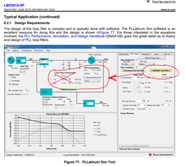
When I load the LMX2615 into PLL sim I get the values in the user manual.

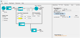
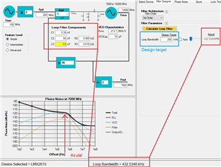
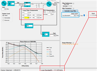
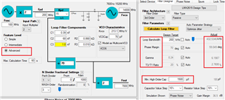
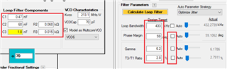
Then when I press calculate they don't agree.

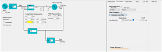
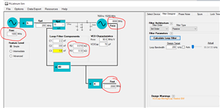
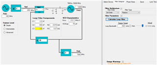
This Diagram shows the values when the LMX2615 is Loaded.

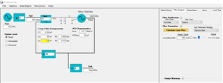
This agrees with the EVM manual.

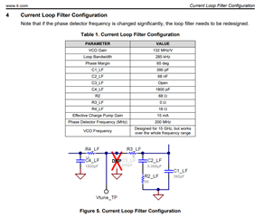
These are the values when I press " Calculate"

  • Hi Paul,

    Simulation is correct and it matches with the test result. The problem is Table 1 is wrong, the Kvco should be 213MHz/V.

    If we change the Kvco to 132 in PLL sim, we will get the same result as in Table 1.

    Thank you for bringing this up, we will fix the user's guide accordingly.

  • Okay so here are the correct values: Could you please confirm?

    and the schematic for the EVM board would need to be updated too correct?

    Also you can see since the calculate button is yellow in the LMX Data Sheet - the values where not calculated.

    So in our design the input is 1GHz instead of 100MHz and our output is 2GHz shown below.

    Could you please run this and confirm you get the same values?

    Since the phase detector frequency is the same (200MHz) as mentioned in the text the values won't change much - only the resistors changed slightly.

    Thanks,

    Paul

  • Hi Paul,

    When the LMX2615 device is selected in PLL Sim, the loop filter is same as the EVM. The loop bandwidth is 432kHz. The 200kHz loop bandwidth on the right window is the default design target in PLL Sim, it is same for all the devices in this tool. 

    If you click the Calculate Loop Filter button, the tool will calculate the loop filter component based on this target. After calculation, the actual loop bandwidth will be shown on the right of the Design Target. For example, after I clicked the button, although my target is 200kHz, the actual is only 111kHz.

    Regarding your design, I got the same result as yours. However, although your target is 200KHz, but the actual loop bandwidth is 94kHz.

    What is your design requirement? Do you have specific phase noise or jitter number you want to hit?

  • Hi Noel,

    Yes I am aware of the target and actual results.

    I will need to look at the phase noise curves of our Crystal Oscillator. We are using 33.333MHz driving your LMK04832-SP generating the 1GHz input to this device.

    Now jumping back to this example with 100MHz in - if you set the target to 432KHz are you able to duplicate the results? I can not.

    When I set the target 432 for Optimize Jitter, Max BW, Min BW and Balance for Spurs I get a Actual BW of 107,228,203 and 122KHz respectively.

    I can't come close to 432KHz. Am I missing something?  

    Thanks,

    Paul


  • Hi Paul,

    There are a few loop filter design constrains hidden in "Simple" level. If you select the "Advanced" level, you will see them.

    In Simple level, you can only change the target loop bandwidth and the tool will design the loop filter for you based on all of these criteria.

    We can manually change these criteria values after uncheck the Auto checkbox. For example, if I put the target values of these criteria same as the original Actual values, the calculated loop filter components is almost same as the EVM value.