This thread has been locked.

If you have a related question, please click the "Ask a related question" button in the top right corner. The newly created question will be automatically linked to this question.

LMK1D1212: How to terminate unused input clock pins of LMK1D1212

Part Number: LMK1D1212
Other Parts Discussed in Thread: LMK1D1208

Hello, 

It is not clear from the Datasheet of LMK1D1212 how to connect the unused Input clock pins. 

On the one hand it is written on page 14 of the datasheet : 

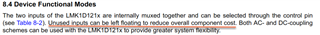
Unused inputs can be left floating to reduce overall component cost.

On the other hand in page 16 written : 

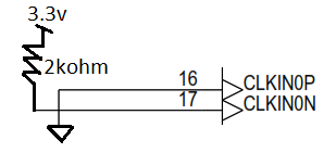
TI recommends grounding unused input Pins using 1-kohm resistors. 

So in the same datasheet there are two different recommendations regard unused input pins. 

Can you please clarify what is the recommended connection  by TI ? (Same question regard LMK1D1208). 

Ohad

  • Hi Ohad,

    Leaving the inputs floating is acceptable and typically recommended by TI. This is because the buffer has built-in hysteresis that allows the floating inputs. Grounding both unused input pins with 1-kΩ resistors may help improve the noise performance, but it is not necessary to do. 

    Thanks!

    Regards,
    Ajeet Pal

  • Hi Ajeet Pal, 

    Thanks for the answer. 

    Another question, if I want to use  LVPECL standard on the input clock for the device, does the clock have to be AC coupled any way like in the picture ? 


    Or can it also be routed directly to the LMK1D1212 without capacitors considering I use the same voltage level for both the driver and the LMK1D1212 ? 

    Now if the clock doesn't have to be coupled with AC capacitors, and the VAC_RF0 and VAC_REF1 are Unused, how shall they then be connected ? Do they stay floating ? 


  • Another Question : 

    Does connecting the Input that way is allowed ? 

    Ohad

  • Hi Ohad,

    For LVPECL input, LVPECL driver and LMK1D1212 CLKin common mode voltage would be different and it would need an AC coupled input. Input should be connected as mentioned Figure 8-5 in datasheet. For AC coupled input, 50ohm resistor at CLKin should be connected at VAC_REF0/1 pins also.

    Does connecting the Input that way is allowed ? 

    What is the use case of above connection? Is it for no input or for unused inputs? 

    For unused CLKin pins, TI recommends grounding both input pins (INP, INN) using 1-kΩ resistors.

    Thanks!

    Regards,

    Ajeet Pal

  • Hi 

    Regard your first answer : You claim that "For LVPECL input, LVPECL driver and LMK1D1212 CLKin common mode voltage would be different and it would need an AC coupled input". But LVPECL common mode voltage is 2v : 

    and according to LMK1D1212 datasheet : 

    It seems Vicm for LMK1D1212 could be 2v (0.25to 2.3) so why you claim the common voltage of LVPECL and LMK1D1212 would be different ? 

    Regard your second question : "What is the use case of above connection? Is it for no input or for unused inputs? " Then the answer is Yes. 

    So is it ok to connect it that way ? 

    Thanks, 

    Ohad

  • Hi Ajeet, 

    can we say in general that the only way to connect LVPECL clock output to LMK1D1212 is that ?  : 

    I would like if you can to have a video conference conversation regard that since I know from my colleague that you helped him choosing that device for the clocks design in our project.  

    Ohad

  • Hi Ohad,

    It seems Vicm for LMK1D1212 could be 2v (0.25to 2.3) so why you claim the common voltage of LVPECL and LMK1D1212 would be different ? 

    The provided common mode range supported by the device but for LVPECL input, there would be higher CM voltage and higher swing. This would need to have ac coupled input. If the applied input LVPECL signal have common mode voltage and swing within the datasheet specified range, it can go with DC coupled input.

    Regard your second question : "What is the use case of above connection? Is it for no input or for unused inputs? " Then the answer is Yes. 

    So is it ok to connect it that way ? 

    I did not get your answer here. For the unused CLK inputs pins, TI recommends grounding both input pins (INP, INN) using 1-kΩ resistors, whereas your connection doesn't show the connections to GND through 1k resistor.

    can we say in general that the only way to connect LVPECL clock output to LMK1D1212 is that ?  : 

    For LVPECL inputs, you can have just right side of the section and others is just depends on the LVPECL driver section.

    Feel free to send me an email, I'll provide to have all queries clarified.

    Thanks!

    Regards,

    Ajeet Pal 

  • Hi Ajeet, 

    I meant by yes that it is for unused input to have there continuously '0' (no) value when no clock is

    Regard the driver side, it is also a TI device with an LVPECL diff output. 

    Ohad

    .   

  • Hi Ajeet, 

    The actual question is what coupling is needed when interfacing between LVPECL diff clock coming from 3.3v Driver to LVPECL diff input in LMK1D1212 receiver powered with 1.8v ?  DC-coupling with voltage divider resistors or AC-coupling with capacitors and using 50 ohm resistors ?  

    Ohad

  • Hi Ohad,

    I meant by yes that it is for unused input to have there continuously '0' (no) value when no clock is

    As mentioned in first reply, you can have any options like floating the unused pins or connect to ground through 1k-ohm resistors. But like you shows the connection may not be recommended as it may induced the different CM voltage at each pins and introduced the noise.

    The actual question is what coupling is needed when interfacing between LVPECL diff clock coming from 3.3v Driver to LVPECL diff input in LMK1D1212 receiver powered with 1.8v ?  DC-coupling with voltage divider resistors or AC-coupling with capacitors and using 50 ohm resistors ?  

    For higher swing LVPECL input, you can go ahead with AC coupled input with series resistors (voltage divider) and 50ohm resistor as shown in figure 8-5. LVPECL driver would have output swing range and compare with the LMK1D1212 input amplitude range.  

    Thanks!

    Regards,

    Ajeet Pal