This thread has been locked.

If you have a related question, please click the "Ask a related question" button in the top right corner. The newly created question will be automatically linked to this question.

LMK05028: How to use GPS PPS as the reference clock to prevent output frequency drift?

Part Number: LMK05028

Hello there

First of all, the purpose of this design is to using the GPS PPS to regulate the PLL of LMK05028 such that the output frequency is free from the temperature change. 

I didn't design the board, so I will do my best to describe it:

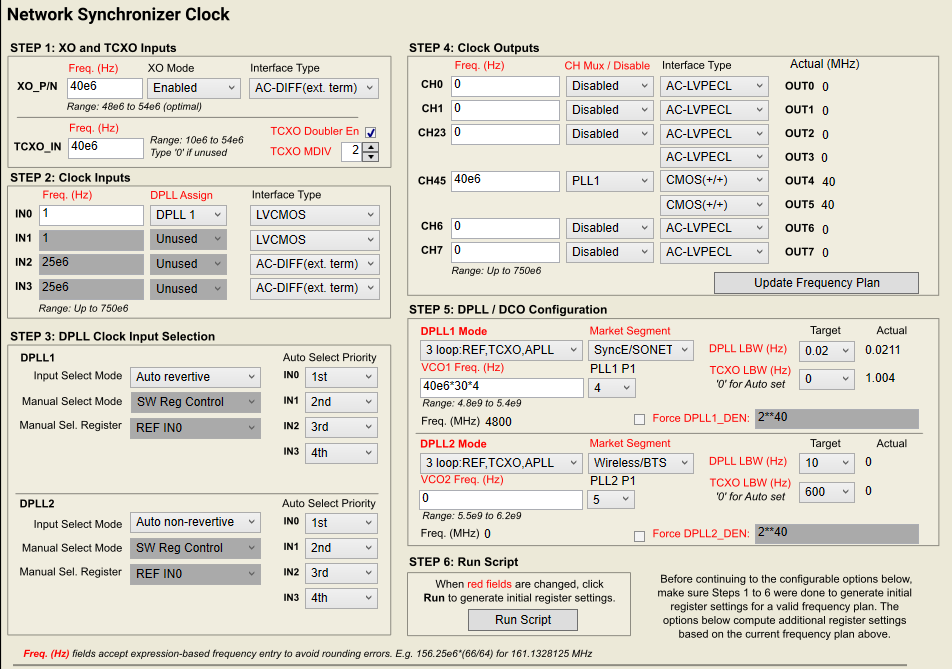
The XO and TCXO is connected to the same 40 MHz clock source;

The GPS PPS is connected to IN0 and then DPLL1

The output is located to CH4 and CH5, and required output frequency is 40 MHz too.

Not sure about the ZMD, maybe not necessary. 

Anyway, after writing all registers using TICS PRO, the status report LOPL_DPLL1,LOFL_DPLL1 and HLDOVR1, so it lost the frequency and phase, and in the holdover mode.

After some modification, not sure what, but HLDOVR1 is gone somehow, but the LOPL_DPLL1,LOFL_DPLL1 are still there.

So what is the right way to configure LMK05028 to be regulated by the GPS PPS?

Is there something related to the duty cycle of PPS signal?

Thanks
  • Hello Xiao,

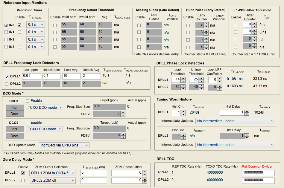
    For a 1PPS input, you will need to enable the 1-PPS Jitter Threshold in order to properly validate the 1PPS input.

    Regards,

    Kia Rahbar

  • Hello Xiao,

    I see that you rejected my answer. Did this not solve your issue?

    Regards,

    Kia Rahbar

  • Hello Kia

    After enabling the jitter threshold, I didn't see anything changed, still no lock

    we have modified the PPS duty cycle to 50% but still didn't work.

  • Hello Xiao,

    It appears that your reference is not being validated. Can you please provide me with your TICS Pro configuration file?

    I will test it in the lab and provide you with a working configuration.

    Regards,

    Kia Rahbar

  • config1.tcsconfig2.tcs

    I have two configuration files, they have different statuses, but neither works, sadly

    thanks for your help, I have been stuck here for a while

  • Hello Xiao,

    I now have a working configuration for you!

    Please follow these steps and it should work on your end as well.

    1. Load this configuration:

    LMK05028_1PPS_config_working.tcs

    2. Press a soft-reset chip.

    3. Readback your status registers.

    It will take about 5-10 seconds for the reference to validate (REF0VALSTAT to go high), about 5-10 seconds for the HLDOVR1 flag to go low, about 20-25 seconds for the LOFL_DPLL1 flag to go low, and about 2-3 minutes for the LOPL_DPLL1 flag to go low.

    Please be patient and continuously readback the status registers until all the flags go low.

    Regards,

    Kia Rahbar 

  • Hi Kia

    I have followed your steps, but still got 

    I made some changes, so only enable IN0 in the validation timer


    and I got some weird stuff

    no holdover, but only REF0 is not validated, and DPLL1 selects REF1 which is unused. 

    after a few tests, I found the validation flags will go high only when the 1PPS jitter threshold is not selected.

    and DPLL1 can never select REF0

    It seems I have a different hardware setup, what else I can try?

  • If disable the 1PPS jitter threshold for IN0

    It can lock something like

    but not the frequency lock

  • Hello Xiao,

    What is the ppm accuracy of your 1PPS reference clock? 

    For your current XO input frequency of 40 MHz and your 1PPS Jitter threshold setting of 63, your reference clocks ppm accuracy must be within 1.575 ppm accuracy. You can determine the required reference ppm accuracy using this equation:

    required ppm accuracy = 1PPS jitter threshold / XO input frequency * 1e6 = 63/40e6 *1e6 = 1.575 ppm.

    Can you also please try the follow:

    1. Load the configuration I provided above.

    2. Enable the TCXO_FDET_BYP and TCXO_DETECT_BYP.

    3. Press a soft-reset chip.

    4. Readback your status registers.

    It will take about 5-10 seconds for the reference to validate (REF0VALSTAT to go high), about 5-10 seconds for the HLDOVR1 flag to go low, about 20-25 seconds for the LOFL_DPLL1 flag to go low, and about 2-3 minutes for the LOPL_DPLL1 flag to go low.

    Regards,

    Kia Rahbar

  • it has a u-blox neo-m8 GPS module and the accuracy of the time pulse signal is 30 ns. It should be fine (right?)

    I am going back to the office on Tuesday next week. will get back to you as soon as possible 

  • Hello Xiao,

    30 ns is fine.

    Yes, please let me know if enabling the TCXO_FDET_BYP and TCXO_DETECT_BYP solves the issue.

    Regards,

    Kia Rahbar

  • Hi Kia

    After enabling these options, I didn't find any difference in the status registers. 

    I am going to try to use the evaluation board later, and see if I can get it right. So I can just click the default configuration button and modify the rest as desired, right?

  • Hello Xiao,

    I would recommend loading this configuration below and then making changes from there.

    3323.LMK05028_1PPS_config_working.tcs

    I was able to obtain successful lock with this configuration on my EVM, so it should hopefully work on your EVM as well.

    Please remember to follow this procedure:

    1. Load the above configuration.

    2. Press a soft-reset chip.

    3. Readback your status registers.

    It will take about 5-10 seconds for the reference to validate (REF0VALSTAT to go high), about 5-10 seconds for the HLDOVR1 flag to go low, about 20-25 seconds for the LOFL_DPLL1 flag to go low, and about 2-3 minutes for the LOPL_DPLL1 flag to go low.

    Regards,

    Kia Rahbar

  • Hello Kia

    I have some more questions 

    1. what is the voltage requirement for the reference clock? can I directly connect the GPS module's PPS and GND output to the IN0_P port, and set the interface type as LVCOMS? I am going to measure the PPS voltage later today.

    2. does the duty cycle of the PPS matter? 

    3. do I need to enable ZDM for frequency stabilization purposes? 

    4. could you provide me with another PPS-lock working EVM configuration which uses the onboard clocks (10MHz TCXO and 48.0048MHz XO)?

    Thanks

  • Hello Xiao,

    1. For a LVCMOS input, the voltage swing must be at least 1 Vpp.

    Yes, you can directly connect the PPS clock to the IN0_P port and set the interface type to LVCMOS.

    2. The duty cycle should be 50/50.

    3. No, ZDM mode is used to achieve zero phase delay between the selected reference input clock and the output clocks of the DPLL. It is not used for frequency stabilization. The DPLLs will use the frequency accuracy of the reference input to determine the frequency accuracy of the output clocks.

    Regards,

    Kia Rahbar

  • Hello Xiao,

    4. Here is the 1PPS config with the onboard XO and TCXO frequencies.

    LMK05028_1PPS_config_40MHz_out_onboard_XO_and_TCXO.tcs

    Regards,

    Kia Rahbar

  • Hello Kia

    I feel so frustrated that my EVM still cannot lock to the PPS. the PPS is set to 50% duty cycle and the voltage is above 3V.

    I was working on it remotely, and one of my colleagues set up the hardware for me.

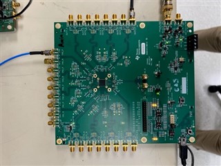
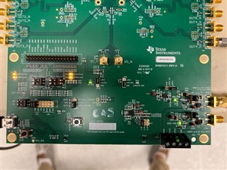
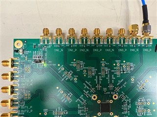
    so could you please take some photos of your EVM showing how the hardware is configured? such as the jumpers and connectors 

    Thanks 

  • Hello Xiao,

    Here are images of my EVM.

    Also I created a new updated configuration for using the onboard XO and TCXO. Please try this one.

    LMK05028_1PPS_config_40MHz_out_onboard_XO_and_TCXO_V2.tcs

    Regards,

    Kia Rahbar

  • Excellent, I will ask my colleague to examine the hardware setup and get back to you.

    Thank you