- Ask a related questionWhat is a related question?A related question is a question created from another question. When the related question is created, it will be automatically linked to the original question.
This thread has been locked.
If you have a related question, please click the "Ask a related question" button in the top right corner. The newly created question will be automatically linked to this question.
Hi,
How can the in chip EEPROM be programmed using an external Host controller. Since as of now the TICSPRO Config file is finalised for a specific frequency plan. Hence, the proper sequence of the steps to do the one time EEPROM programming for this specific config file is required?
Hi Akanksh,
Section 9.5 of the LMK5B12204 datasheet has detailed instructions for programming the device, including how to program the EEPROM. Typically you can use the TICS Pro configuration to export an associated hex register map, and this information can be programmed by an external controller into the device through I2C or SPI. Let us know if you need more details or have other questions.
Thanks,
Evan Su
Hi Evan,
As per my understanding from the section of the datasheet and the steps under process in the TICS Pro application. There are multiple other registers which are written before programming EEPROM from SRAM.

I find only the above step relevant, before the EEPROM program from SRAM. Whereas R159, R160 and R162 are written multiple times into the register. Is it a necessary step, since the description in the register spec is also unclear for these registers?
Hi Akanksh,
There are two methods of writing to EEPROM: REGCOMMIT and SRAM Direct Write method.
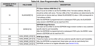
TICSPRO writes the registers noted in Table 9-9 using the SRAM Direct Write method (this method is required to program these registers). TICSPRO then performs the REGCOMMIT method.

Please refer to this detailed guide and let me know if something is confusing.
LMK5B12204_LMK05318B EEPROM Programming Methods_dec 16 2022.pdf
Regards,
Jennifer
Hi Jennifer
Yes this document clarifies the EEPROM programming related questions.
Now once the EEPROM is programmed, what are the registers to be toggled or written as the process of default start up sequence. The following steps are what I understand is required:
1. After power on, perform a soft reset.
2. Read the status registers to confirm if reference is validated, and check Lock of DPLL phase.
3. Toggle the SYNC_SW from 0 ->1 -> 0.
4. Perform the DCO Increment/ Decrement to the output( if any).
5. Read status registers for loss of reference at specified time intervals.
Hi Akanksh,
The device power-up sequence is shown in Figure 10-1. The device handles most of it automatically and end user is not required to do much for the device to start working, however for complicated devices like DPLLs it is good to periodically monitor the status and use the optional features if suitable.
> After power on, perform a soft reset
I don't think this is needed, because starting from power-on will take the device through a hard reset, and it will end up in the Device Block Configuration state, which is the same state that a soft reset is a shortcut to.
> Read the status registers to confirm if reference is validated, and check Lock of DPLL phase.
This is not required but confirms if the device has successfully locked, which is good to know.
> Toggle the SYNC_SW from 0 --> 1 --> 0
This will help synchronize the outputs, optional but may be helpful depending on the application.
> Perform the DCO Increment/Decrement to the output (if any)
I am not very familiar with this feature but I believe it is for precise clock steering in applications requiring very high synchronization/precision.
> Read status registers for loss of reference at specified time intervals
Not required but good practice to monitor the behavior of the DPLL even after the startup sequence and be alerted if there is a problem.
Best,
Evan Su