This thread has been locked.

If you have a related question, please click the "Ask a related question" button in the top right corner. The newly created question will be automatically linked to this question.

CDCE925: clock signal arrangement and ppm error

Part Number: CDCE925
Other Parts Discussed in Thread: CLOCKPRO

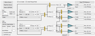
I am using your clock pro 1.2.1 software to generate three clock 20MHz, 7.3728Mhz and 30.72MHz from 10Mhz input clock, software selected CDCE925pwr chip and assigned these three signal to Y5, Y3, and Y1 with all 0 ppm error. Such as 7.3728MHz assigned to Y3 with "0  ppm"  and "No PPM error" message, but if I set PDIV2 also 25, as same as PDIV3, Y2 is changed to 7.3728MHz,  but message under it is "infinit ppm" and "0", does it mean Y2 also has 0 ppm error? 

if I used software wizard to generate four clock 20MHz, 7.3728Mhz and 30.72MHz, 7.3728MHz, software generate 30.72Mhz and 7.3728 Mhz together from same source, not two 7.3728MHz together, any special reason for it? thanks.

  • Hi Harry,

    ClockPro is an old piece of software that we are planning to update or replace in the future. The "PPM error" feature is often inaccurate and I would not pay much attention to it as long as the output frequencies are what you are expecting; you can dismiss the errors with the "Reset PPM Reference" button.

    if I used software wizard to generate four clock 20MHz, 7.3728Mhz and 30.72MHz, 7.3728MHz, software generate 30.72Mhz and 7.3728 Mhz together from same source, not two 7.3728MHz together, any special reason for it? thanks.

    I tried this out and in my case ClockPro generated 2x 7.3728 MHz and 1x 30.72 MHz from the same source:

    Structurally, Y2 and Y3 are paired so that they need to come from the same source (either PLL1 output or reference bypass), and Y1 is not paired with anything. But with the current mux settings, Y1 + Y2 + Y3 are all coming from the output of PLL 1 so there should not be a problem.

    Best,

    Evan Su