This thread has been locked.

If you have a related question, please click the "Ask a related question" button in the top right corner. The newly created question will be automatically linked to this question.

LMK5B33216EVM: RMS jitter is higher than expected

Part Number: LMK5B33216EVM

Hello,

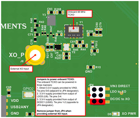
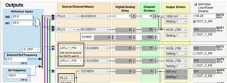
We're trying to analyze the phase noise of our LMK5B33216EVM board. We're using an SIT5347AE-FN-33E0B100.000000 MEMS oscillator, producing a 100 MHz signal, which is connected to the Y3 blueprint on the evaluation board:

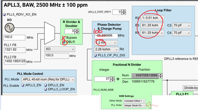
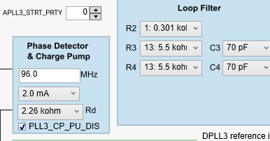
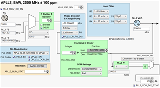
We're producing a 156.25 MHz output, using only APLL3 (DPLL disabled), with these settings in TICS PRO:

However, when measuring the phase noise with our E5052B signal source analyzer, we observe a larger RMS jitter than expected when compared to the datasheet (with noticeable spurs at higher frequencies, far outside the loop filter bandwidth):

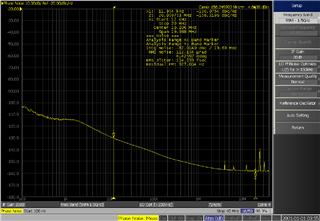
Could you advise us on what may be the source of our issue - in particular, the high frequency spurs? Thank you in advance!

Best,

Joel

  • Hi,

    Do you have intention of using the DPLL?  If not, configure APLL3 more optimally to have 100 MHz phase detector frequency.

    Note default settings are which I would suggest for the charge pump and loop filter values.

    If you want to use DPLL, you should have a non-integer relationship between XO and VCO frequency for DPLL to be able to avoid integer boundary spurs.  This is not true with the 100 MHz direct, however it appears you were aware of this and configured for *2 /3 so that 2500 MHz / 66.66 = 37.5.  This does indeed avoid the integer boundary, although there may be some 2nd order effects.

    • FYI, the PLL phase detector is operating at a lower frequency and hence not as good.
      • However seems to this end you attempted to minimize loop bandwidth by reducing the charge pump current.  Since the PLL charge pump PUMP UP is disabled, you should consider increasing the Rd resistor value some due to lower current.  (You may also choose to simply enable the PUMP UP by unchecking the "PLL3_CP_PU_DIS"
      • So this may not be your issue so much.
    • It looks like there is some elevated noise above the loop bandwidth, this may be the result of the high resistor values on R3/R4.  Try reducing.

    Do you have other clocks operating at different frequencies close-by which could be crosstalking?

    Were you able to remove power from the primary TCXO for EVM?  You should have only on XO powered.  See info below:

    Oscillator Designator

    Example Part Number

    Type, Package

    Power Resistor

    Localized 0.1 uF bypass

    RF output resistor

    Y1

    7N48071001

    Common 7.0 mm x 5.0 mm, 4 or 10 pin

    R206

    C80

    R43

    Y2

    8W48072003

    Common 2.5 mm x 2.0 mm, 4 pin

    R207

    C82

    R46

    Y3

    7X-50.000MBB-T

    Common 3.2 mm x 2.5 mm, 4 pin

    R208

    C83

    R47

    Y4

    ROM9070PA

    OCXO, 9.7 mm x 7.5 mm, 4 pin

    R209

    C84

    R48

    Y5

    ROX2522S4

    OCXO, 25.4 mm x 22 mm, 7 pin

    R210

    C85

    R49

    73,
    Timothy

  • Hi Timothy,

    Thank you for the prompt response! We do intend to use the DPLL eventually, which is why we chose those parameters to avoid the integer boundary.

    I tried adjusting the values of R3 and R4 as well as unchecking PLL3_CP_PU_DIS, but I still see an RMS jitter of around 115 fs with the high frequency spurs in the phase noise plot. Also, I don't believe we have any other active clocks or XOs on the board that may be interfering with our MEMS oscillator or APLL3 output.

    We plan to test our setup using a new LMK5B33216EVM board without any modifications, just to compare against our board with the MEMS oscillator and to verify that our lab setup (power supply, phase noise analyzer, etc.) is correct. We'll keep you updated if we can locate the source of our high jitter and spurs - thank you again!

    73,

    Joel

  • Hi Joel,

    I checked with your TICS Pro settings with 100 MHz from sig gen SMB100A and did not observe that high rms jitter on the output. Let us know if your new board could get better PN.

    -Riley

  • Hi Timothy and Riley,

    Thank you again for your feedback on this question. We realized that we were using OUT0 for our output, which is DC-coupled. We switched to OUT4 to generate an HSDS signal, and now we're getting an RMS jitter of ~53 fs for both evaluation boards, which is much closer to our expectations. Thank you again for the assistance - we really appreciate it!

    Cheers,

    Joel