This thread has been locked.

If you have a related question, please click the "Ask a related question" button in the top right corner. The newly created question will be automatically linked to this question.

LMX2694EPEVM: Harmonics and frequency stability.

Part Number: LMX2694EPEVM

I have an LMX2694EPEVM that I am attempting to output 3GHz. the output frequency is a few MHz off and continues to drift as time goes on. I also have large 2nd and 3rd order harmonics. The reference oscillator is a 10MHz signal from an FSVA3013. This is a very clean reference so I'm a bit confused about frequency drift/accuracy on the output. 

  • David,

    The three most likely possibilities I see are:

    1. Input Reference is drifting

    If your input reference were to drift say 10 kHz, which is 0.1%, then this would translate to 3 MHz at 3 GHz.  This would be assuming the PLL is locked.

    This FSV3013 seems like a fancy piece of test equipment, but maybe there could be an issue if it had some setup issue, like being told to SYNC to another piece of test equipment and no signal to SYNC to this.

    2. PLL is not really locked

    The VCO is divided into 7 cores, each one has about 192 bands, so that's over 1000 bands in the VCO.  When you calibrate the VCO, the loop filter is disconnected and the proper band is found.  Now if the loop filter was say shorted or disconnected, then this voltage would be held constant and one could be deceived into thinking the PLL was locked.  But if you look at lock detect, tuning voltage, or the close-in spectrum, then it would be clear that you are not locked.  Can you verify that for sure the PLL is locked.

    3.  Sensitivity issue with input reference

    If the 10 MHz is low amplitude, then maybe the PLL is missing counts.  If this was the case, I would expect the spectrum to not be clean close in.  Also, more often than not (but not always), the PLL will lock low in this case.

    Regards,

    Dean

  • Dean, 

    Thank you for the reply. I checked a few things and I'll step through your suggestions.

    1. The input reference is right at 10MHz and +10dBm. Verified this with another Spectrum Analyzer. 

    2. The lock detect pin has not gone high. Once the VCO calibration is complete, should I see 3.3V? What would be a good way to check the loop filter for shorts/opens?

    3. Again, the input reference is +10dBm. 

    This is quite a bizarre thing. I have tried resetting the device and after writing registers I will get different results. Sometimes a signal at 2.95GHz. Sometimes a signal at 4.15GHz. Sometimes a low signal at 8.2GHz. Sometimes no signal at all. I am following the manual's directions for programming the device. I see similarly sporadic behavior on a second board as well. I feel like I may be doing something wrong, but not sure what.

  • HI David,

    If you have LD_TYPE = VCOCal, when VCO calibration is complete, lock detect will turn HIGH (3.3V, if you have MUXOUT_LD_SEL = 1). 

    If LD_TYPE = Vtune and VCOCal, lock detect will turn HIGH only if VCO calibration is complete AND Vtune voltage is within range.

    If it is locked, Vtune voltage should be around 1.25V. 

    You could also try with a 10MHz square wave or keep using the signal generator but make its output to 100MHz. Use the R divider to make the phase detector frequency same as if using 10MHz reference clock. 

  • Dean,

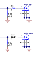
    Thanks Again. I discovered that when reference signal is connected to OSCINP, the output signal is as expected. I have had my reference signal connected to OSCINM. I was under the impression that these two inputs were identical. Is that not the case?

    Anyway, I was able to reliably get a stable 3GHz tone and 3V at the lock detect pin after switching the input connections. 

    Ian

  • Hi David,

    OSCINM is not connected to the pin of the IC.