This thread has been locked.
If you have a related question, please click the "Ask a related question" button in the top right corner. The newly created question will be automatically linked to this question.
Hello
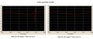
We have a design that uses the LMX2572 with full assistance. This works but not reliably. The problem appears to be the value read from register 112 (VCO DAC) during calibration. From the data sheet the upper 7 bits would be expected to be all 0s. However, most chips return all 1s. Some chips (that give us problems) return 0 for bit 11 others 0 for bit 15. If we use these values then we find the chip does not lock over some parts of the band. If we simply force all 7 bits to 1 then all appears OK. Generally we see the problem around 5.4 GHz.
We have not tested a large enough number of chips to give us confidence that our solution is reliable. Particularly as the solution is not in line with the data sheet.
So, my question is whether anyone else has come across this problem and if so, how it was solved.
Thank you.
Hi Nils,
Can you share your config (.tcs) file?
What is your input?
Regards,
Vicente
Hi Vicente
We are not using the Ti eval board. These are our own boards with our own controller. Just to confirm, all works fine in normal (auto cal) mode. Also during the calibration run, we can see lock is achieved at every frequency. So, no problem there either. My question is about what reg 112 returns, in particular the upper 7 bits. As you know, the read values of reg 112 during calibration are then used to write to reg 16 in fully assisted mode. Have you looked at what the read values of reg 112 look like with the eval board? Do they look as expected from the data sheet?
Thank you and regards
Hi Nils,
On my EVM I was able to generate a 5.4 GHz output by directly outputting VCO freq directly.
The bits listed as zero in DS are read-only bits. If you read back different values for these upper bits, it is not a cause of concern given, they're read only. For the same reason if you write to these bits and make them all 1, nothing is actually being written to the device given the bits are protected from writes.
To ensure you're reading back correctly, did you configure MUXOUT_LD_SEL = 'Readback'?
If this is not done, you won't read back from the device.
Regards,
Vicente
Hi Vicente
Thank you for taking the time to reply. We are pretty sure we are reading back OK otherwise the calibration would never work at all. I think the answer to our question is not in the data sheet. Certainly, we found that in fully assisted mode it does matter what you make the upper bits when you write to reg 16, regardless what the data sheet says. I think it would be good to hear from someone who has implemented the fully assisted mode over the entire band.
Thanks again.
Hi Nils,
R16 has upper bits bits[15:9] as R/W. They should be set 0x0h. Writing to these bits in that can can be of effect.
Please try the following:
Program LMX2572 to lock to the problem frequency with auto cal.
Read back VCO parameters
Apply full assist on-the-fly, that is
If the above sequence works, then do a power cycle and then program LMX2572 again with full assist using the above readback data.
Regards,
Vicente
Hi Vicente
Thanks. Yes, we have read the data sheet and assisted mode application notes many times
Anyway, setting all upper 7 seven bits to 0 as you suggest does not work. Some chips fail to achieve lock around 5.7 GHz.
If we force all the bits to 1 then all seems well. Here is a picture that gives an indication if the PLL is working and locked from 3.2 to 6.4 GHz. With the bits set to 0, you can see a band around 5.7GHz where the trace breaks up (i.e. no PLL lock).
Hi Nils,
Can you please attach your config (.tcs) file so I may test on my end.
Regards,
Vicente