This thread has been locked.

If you have a related question, please click the "Ask a related question" button in the top right corner. The newly created question will be automatically linked to this question.

LMX2491: Discontinuity in the ramp

Part Number: LMX2491
Other Parts Discussed in Thread: LMX2492EVM

We are using the LMX2491 in combination with a 24GHz Radar Frontend what has a divide by 16 output for an FMCW radar. For this we need the ramp/chirp feature of the PLL chip itself. I've now optimized the loop filter for CW to get a tradeoff between phase noise and spur suppression but when I switch to a 30M ramp I can clearly see some discontinuties in the TX signal of the frontend.

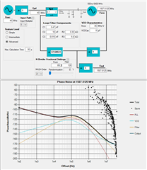
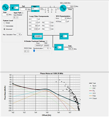
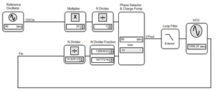
Here is the PLL simulation:

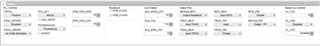
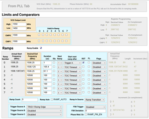
And here the settings what I use for the TICS:

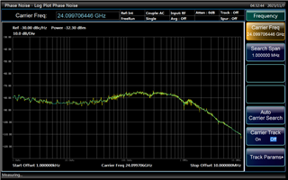
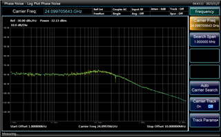
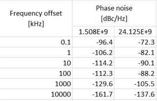
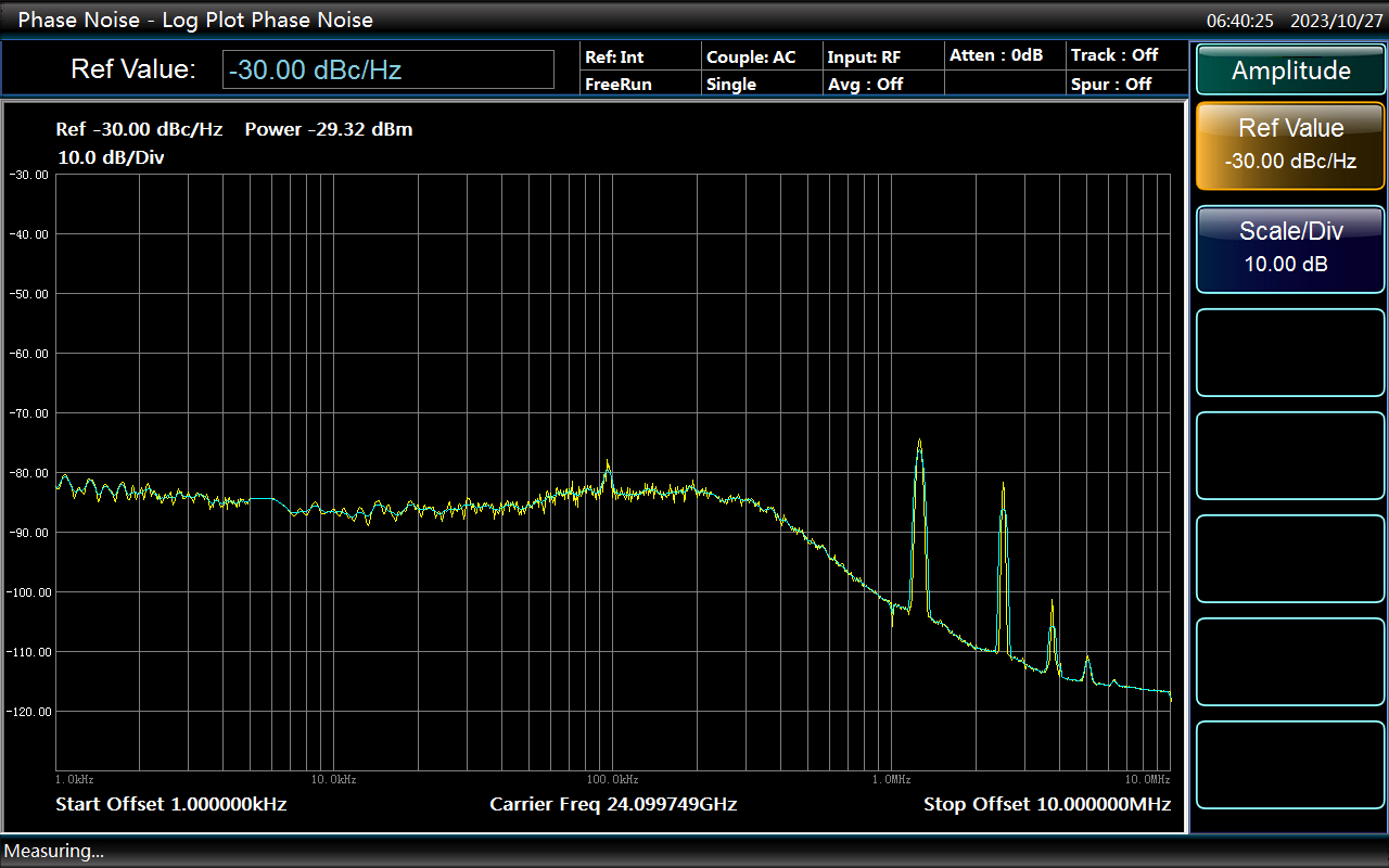
Here is the phase noise plot in CW mode for 24.1GHz TX:

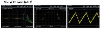
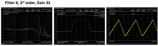
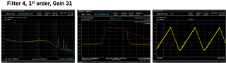
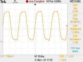
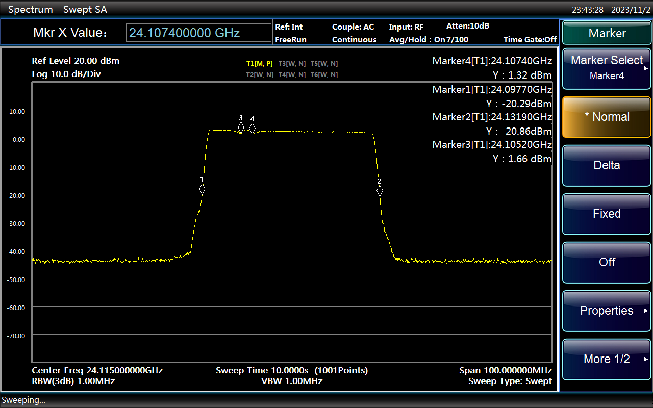
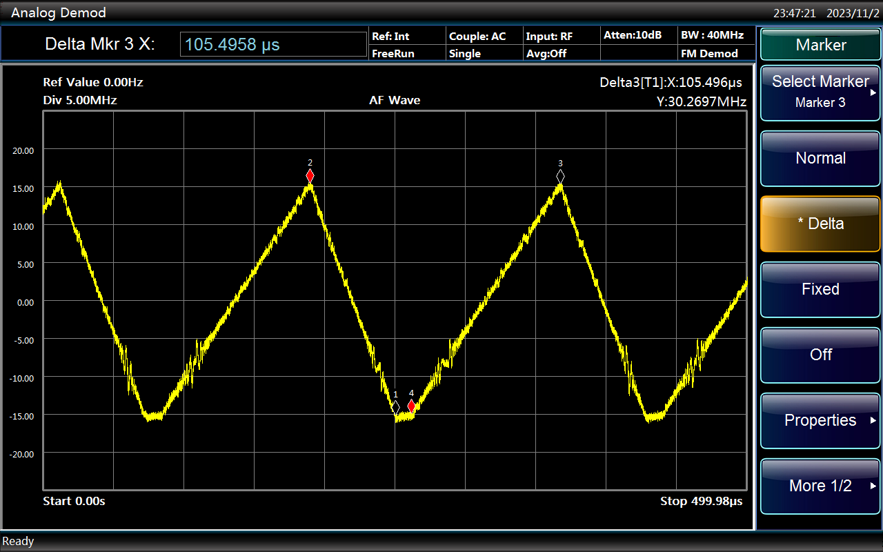
And here is the measured TX power over time and a demodulated measurement for the ramp:

I've tried different settings and noticed that a lower charge pump gain will give me also less spurs and noise in the ramp itself. Further I tried to work with different FRAC_ORDERS but only order one is working in my setup. As soon as I use order 2 or 3 it looks like the loop filter gets unstable.

Does anyone have any idea what the reason could be for this behaviour? 

  • Hi Ueli,

    Based on your pll configuration, you will have fractional spurs at multiple of 625kHz. 

    You can get rid of it if you can change the reference clock frequency to, say 38.4MHz. 

    We seldom use 1st or MASH, as this configuration will usually create big spurs. 2nd or 3rd order MASH is recommended. 

    Again, based on your configuration, you should be able to get a smooth ramp up/down plot. You may try to increase the loop bandwidth to see if that helps.

  • Hello Noel

    Thanks for your feedback. I can only work with 40MHz as reference but I will do some testing here with the doubler an reference divider to shift the compare frequency. 

    I did another test with a different filter and gain setting where I've changed only the FRAC_ORDER:

    I can see a lot more spurs with FRAC_ORDER 2 or 3 compared to FRAC_ORDER 1.

    I've also done tests with a loop bandwidth of 500kHz instead of the 100kHz but this makes the problem even more worse because the filtering of the spurs at higher frequencies is also getting more worse.

    Do you have any other ideas?

  • Hi Ueli,

    Looks to me the discontinuity is due to 1st order. 


    When using 2nd order mash, change a different PFD_DLY value or enable FRAC_Dither to optimize spurs and phase noise. 

    Check if below design can reduce the spurs more.

    e2e2491.sim

  • Nello Noel

    Thanks for sharing your simulation with me. I've done some further testing with a compare frequency of 40MHz without the usage of the internal doubler. Here I get the expected results when I work with FRAC_ORDER 2 or 3. I need to do some more testing here but it looks that your suggestions to change the PFD_DLY and FRAC_Dither mode can further help. The problem what I actually see is that the phase noise is app. 10dB higher than it was for the 80MHz compare frequency.

    Do you have an idea why the higher fractional orders are not working in combination with the reference input multiplier for a compare frequency of 80MHz?

  • Hello Noel

    At the moment I'm working with the following filter (fcomp = 40MHz, Gain = 31):

    I've done measurements for the fractional order 2 in combination with all possible dither and delay settings. I get the best result with a delay of 1500ps independent of the dither setting:

    Further I've done the same for fractional order 3 where I get the best result with a delay of 1200ps with all dither setting excluding disabled:

    This works well for the ramp itself but the phase noise is far away from the simulated one when I compare the simulated closed loop gain @ 24GHz with the measured results:

    We should come down to -88.2dBc/Hz @100kHz but in reality I'm @ -74dBc/Hz @ 100kHz. The phase noise itself was app. 10dB better with a compare frequency of 80MHz but there modulator order 2 & 3 are not working.

    Do you have any idea what could be the reason for this or how I can improve the phase noise to com more towards the simulated value?

  • Hi Ueli,

    Dither will randomize the spurs while PFD_DLY will create an intentional phase difference in phase detector.  As a result, spurs will be smaller but phase noise will get worst. 

    There is a limitation to optimize spurs/phase noise performance by just using PLL configuration, you may need to make use of the loop filter to help reduce the spurs more. Since those spurs are generated from the PLL, loop filter can reduce the spurs, also smaller charge pump current will result in smaller spurs. I prefer to use 80MHz fpd with a smaller charge pump current in the design. 

  • Hello Noel

    I also want to use 80MHz but as soon that I enable the internal multiplier I can't work with fractinoal order 2 or 3 because spurs are getting much worser than with fractional order 1 and I see a complete different behaviour as when I work with 40MHz. Do you have any idea what can cause the behaviour what I see with a compare frequency of 80MHz? Why is there such a big difference working with modulator 2 or 3 in comparison to a compare frequency of 40MHz?

    Further I've also not only tried to optimize the PLL configuration by the change of settings. I've simulated and soldered in 8 different loop filters and tried to optimize it with all your suggestions. I get a usable solution with 40MHz compare frequency with no spurs in the ramp but the phase noise is far away from the simulated one.

    When I work with 80MHz as compare frequency I can get a phase noise what is nearly the same as the simulated one but there I have big problems with spurs when I work with fractional order 2 or 3 and I can't get a smooth ramp.

  • Hi Ueli,

    Where is the 40MHz clock coming from? What kind of format it is and voltage swing?

  • Hello Noel

    The 40MHz clock comes from anoscillator with a 3.3V supply (KC2016K40.0000C1GE00) and is fed single ended into the reference input over a voltage divider of 220R/680R followed by a 100nF capacitor. The negative OSCin pin is terminated with a 100nF capacitor followed by a 680R series resistor.

    I already tried to work with factor 10 lower resistors to increase the slew rate what had no effect. A reduction of the voltage swing to app. 1.8V had also no effect.

  • Hi Ueli,

    Can you try below? Shunt the unused OSCin* to ground via a 0.1µF capacitor.

  • Hello Noel

    At the moment I use a 100nF capacitor followed by a series resistor to GND as suggested in the datasheet. I used the same impedance for the resistor what is seen by the positive OSCin port. So do you mean to use only the capacitor and shunt it directly to GND?

  • Hi Ueli,

    Yes, shunt it to GND without the resistor. Since you already have that resistor in the layout, you can try with or without the resistor, see if there is any difference.

  • Hello Noel

    I tested your recommendation and can't see any influence at all. I've now a TI LMX2491EVM on my table and changed there the 100M reference oscillator to a 40M one out of the same series as the 100M. I can observe the same problem there when I want to work with a 80M compare frequency.

    I've now saw that the LMX2491EVM is not working at all with the 100M reference input and a compare frequency of 100M. I've now saw in the PLL Sim that the N divider value gets red when I want to go for 100M as compare frequency. I now found in the datasheet that there is a limitation for the N divider depending on the used modulator order (Table 1 in the datasheet).

    Can it be that the LMX2491 does not work at N divider ratios what are quite near at the allowed minimum?

    So here I can clearly see that modulator order 3 has a minimum of 19 and with my settings with a compare frequency of 80M I will have a N divider of app. 18.8777. But in the simulation I won't get any error at all when working with a MASH Order of 3 and my divider setting. Is this a bug?

    Further I've also found a strange thing in the PLL simulator tool: When I change for example the charge pump current, the tool will always reset the Kvco value to a default of 20MHz. Is this a also a bug?

    The VCO on the LMX2491EVM works from 1400 to 1624 MHZ and the frequency what I need is somewhere around 1500MHz. Is there a recommendation for the settings for the LMX2491EVM to work in this band?

  • Hi Ueli,

    the minimum N restriction has to be obeyed otherwise the PLL may not lock. Apologies, I overlooked this restriction. N=18.8777 may work, but I recommend not to use this setting to avoid part to part variation.

    Both TICS Pro and PLL Sim was developed long time ago, the min. N restriction was not implement in these tools. I will inform the developer to fix this issue.

    I also found it annoying that he Kvco will change unintentionally. I need the developer to fix this issue as well.

    There is no LMX2491 EVM, we only provide LMX2492 EVM, and the onboard VCO is 10GHz. Check the EVM user's guide for the schematic and then modify it to work with a 1.5GHz VCO (U2p, not populated).

    Basically, we need to remove R4_LF, populate R4pLF so that Vtune will go to U2p. We also need to remove the power supply to U2.

  • Hello Noel

    OK we will work with the 40MHz setting what seems to work quiet well.

    Yes it would be great when you guys could fix this two bug's in the PLL Sim Tool because it was quiet confusing for me to find out the reason why we got so different outputs and we lost the trust into the Sim Tool and also a little bit into your PLL's aswell.

    But as far as I know TI recommends the usage of both tools for their PLL's and Synthesizers. So in my opinion this should not make any difference for a customer when the tools were developed long time ago.

    You are right there is only the LMX2492EVM what we sourced and I did exactly the changes what you've suggested to change it to a LMX2491EVM. Are there any suggestions for the settings to work with for the LMX2491EVM when it comes to the maximum compare frequency? I know you are working there with a 100MHz reference but it would be interesting what settings you recommend for the setting in this evalkit.

  • Hi Ueli,

    If VCO is just 1.5GHz, the max. fpd will be limited by the min. N restriction. With 3rd order MASH, min. N is 19, so the max. fpd we can use, with a 100Mhz input clock, is 50MHz. This is pretty much the same as your real application configuration.