This thread has been locked.

If you have a related question, please click the "Ask a related question" button in the top right corner. The newly created question will be automatically linked to this question.

LMK62E2-100M: Questions about NC and OE pin timing

Part Number: LMK62E2-100M

hello. I'm Su-Yeong.
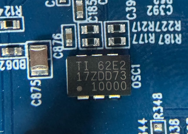
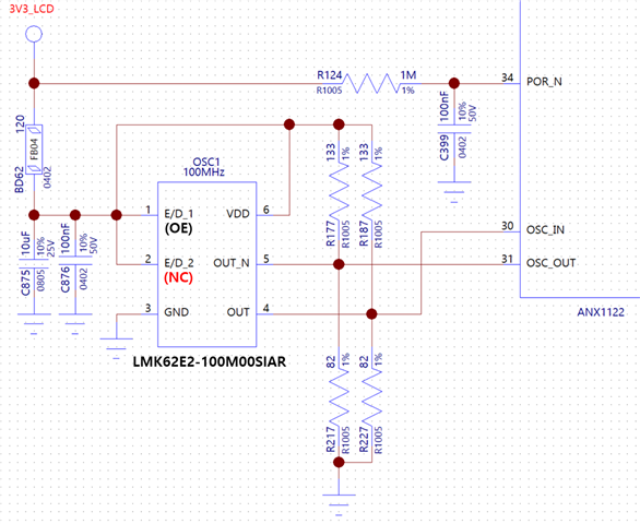
We are currently using 'LMK62E2-100M00SIAR', and our schematic is as shown below,

with NC and OE pins tied high at the same time as VDD.

My question is as follows
1. Does the NC pin have no circuit inside? If it is tied High like our schematic, does it affect the behavior?
2. The OE pin is tied High at the same time when the power is turned on. Is there a power sequence that VDD and OE should follow?

Thanks.

  • Hi Su-Yeong, 

    I would recommend leaving the NC pin floating if possible, but if it's tied high there shouldn't be any impact to the device.

    It's ok to ramp OE and VDD at the same time, but it's recommend to add a pull-up resistor (something in the range of 1K-10K Ohm should be fine) to minimize leakage current. 

    Regards, 

    Connor 

  • Hi Connor.

    Thank you for your quick response.

    I have one more question.

    In my initial circuit design, I applied the reference circuit of 'ANX1122' and the OSC is 'LMK62E2-100M' from TI.

    Is it okay to apply the pull-up(133 ohm) and pull-down(82 ohm) of the Thevenin circuit applied to OUTN and OUTP like this?

    Our purpose is to regulate the level of the signal with a Thevenin circuit, is it possible to influence the operation of the OSC?

    Thanks.

  • Hi Su-Yeong, 

    Based on the intermittent behavior described in this thread(https://e2e.ti.com/support/clock-timing-group/clock-and-timing/f/clock-timing-forum/1309546/lmk62a2-266m-lmk62e2-100m-osc-does-not-work-intermittently) I'm actually checking with the design team to make sure there's no impact when NC and OE are both pulled high. I should be able to give an update early next week. 

    In terms of the termination network, the datasheet recommends a 150 Ohm to GND termination on both OUT_P and OUT_N for normal LVEPCL levels. The Thevenin termination you have should work but it might shift the output amplitude and common-mode voltage from the typical values given on the datasheet. 

    Regards, 

    Connor 

  • Hi Su-Yeong, 

    After speaking with the design team, there is some risk that the intermittent behavior is from the NC pin being pulled high. This pin is used internally as a test point during production at the factory, and the device can have unpredictable behavior if it's being pulled high. The design team is still checking to see exactly what state the device will go into when the NC pin is pulled high during startup. Is it possible to change the board design to leave the NC pin floating?

    Also, can you share the top marking of the device you are using?

    Regards, 

    Connor 

  • Hi Connor,

    Unfortunately, the design of the board cannot be changed.

    Can you share with us what kind of tests the factory does with NC pins? In our test jig, we are testing the on-off aging of a new OSC with the NC pin and VDD tied together, But we have not found any issues yet.

    When can I expect to have an answer on what the design team's checking?

    The attached photo is the top marking of the OSC with the problem.

    Thanks.

  • Hi Su-Yeong, 

    Thanks for sending over the photo with the top marking.

    The NC pin is used internally as a communication line and analog test point for a few different features inside the device. The design team said there's a risk that on power-up this pin is being sampled and putting the device into a debug mode where the output clock is disabled. It may take a few more days for them to look through the design and confirm if this is the issue, I will try and give another update early next week. 

    Regards, 

    Connor 

  • Hi Connor,

    We found one peculiar thing that is independent of NC pins.

    While testing in our test jig, we recreated a situation where OSC was not working. This phenomenon occurs with a very high probability at sub-zero temperatures (-10 ~ -20℃) when the settling time of VDD is about 1.3ms ~ 7ms. It does not occur when the settling time is shorter or longer than this. This result is the same when the NC pin is tied to VDD and when it is floating. It is also reproduced on marking 62E2 17ZDD73, but not on marking 62E2 3BZER83.

    There is nothing in the datasheet about the timing of the power source. Check with your design team to ask if they have any guidance on timing.

    I hope this helps in your process.

    Thanks.

  • Hi Su-Yeong, 

    Thanks for the update. Our design team confirmed that the NC pin should not be causing this type of behavior. 

    We released a new die revision for LMK62E2 in May 2021 that has improved startup reliability, especially at cold temperatures. It looks like the unit you are seeing issues with was produced in 2017, and the unit that has no issues was produced in 2023. If possible, I would recommend switching out all devices that have the old datecode (the first 1-2 digits on 2nd line of device marking give the production year) with new units. 

    Let me know if you have any other questions. 

    Regards, 

    Connor 

  • Hi Connor,

    Thanks for the answer. I have one more question.

    Did the product before the May 2021 release have startup timing issues at cold temperatures? My test data suggests that this is closely related to power timing with temperature.

    We are not able to replace parts as many boards have already been produced, but we can update the software.
    One alternative is to reset the converter to power the OSC in the event of an I2C communication error, since the CLK is not output from the OSC after startup. We have already verified that this behavior works. We need your opinion on this idea. 

    Thanks.

  • One more thing.

    The parts we used for the board are from the 26th week of the 21st year. (Lot No. : 1964462CL1)

    Is this 62E2-17ZDD73 product a 2017 die vision? Please tell me how to interpret the 17ZDD73 and 3BZER83 markings on the product.

    Thanks.

  • Hi Su-Yeong, 

    Yes, the previous die revision was sensitive to cold temperatures and sometimes didn't startup correctly like you're describing. I think it should be valid to power cycle the device until the output clock is outputted normally, as far as I'm aware the issue only happens at the initial device startup. Another solution is to screen out the older material by power cycling 10 times at cold temperature and seeing if any failures occur. If a device passes startup 10 consecutive times then most likely it will not have the startup issue at cold temperature. 

    To decode the device markings, it looks like only the first digit is used for the year, and the 2nd digit is used for the month. So the device that starts with "17" was assembled in the 7th month of 2021 and uses the old die revision, and the device that starts with "3B" was assembled in the 12th month of 2023 and uses the new die revision. 

    I'm actually seeing conflicting information about when the new die revision was implemented, another source says it actually began production in 4Q2021. To be safe, for future builds it would be best to make sure the assembly date is at least from 2022 or later, or the screening procedure with at least 10 power cycles is performed. Let me know if this answers your questions. 

    Regards, 

    Connor 

  • Hi Connor.

    Thank you for your answer. We request precise information on a few things in order to define this issue more clearly.

    1. The exact timing of production of the revised New Die.(Confirmation of conflicting information)

    2. What is the approximate degree of 'Cold temperatur'?

    3. What was the percentage of defective parts before the new die was revised?

    I will wait for your reply.

    Thanks.

  • Hi Su-Yeong, 

    1. The new die revision started production in 4Q2021, it is recommended to use devices with an assembly date of 2022 or later

    2. It would be best to perform the screening procedure at around -40C to screen out any sensitive devices. Device failure could occur at temperatures warmer than this, but the chance of failure is significantly lower at higher temperatures. 

    3. The percentage of defective parts using the old die is not known for certain since there's a very limited sample size of failing devices. We have not seen any failures with the new die revision. 

    Also just to confirm, have you only found 1 defective unit so far? Or are there multiple failing devices? 

    Regards, 

    Connor 

  • Hi Connor,

    Thanks for the reply. We currently have only one malfunctioning OSC, and two suspected cases with the same symptoms reported in the field, but not yet returned.

    This is a different question, when you test with the NC pin in the production factory, how do you test? Do you put a command on the NC pin? or input a specific clock to the NC pin? And am I right in thinking that this issue has nothing to do with NC Pin?

    Thanks.

  • Hi Su-Yeong, 

    Understood, thanks for the information. Feel free to give an update with the top marking of the two additional devices once they arrive if they are having the same issue, and I can check the lot information to make sure they are also using the old die revision. 

    The NC pin is used as an internal I2C line and test point during production, according to the design team pulling the NC pin high should not be causing any issues. 

    Regards, 

    Connor 

  • Hi Connor,

    Thanks for sharing the information. The two devices reported in the Field are either 17ZDD73 or 7AZC1E3. We confirmed that both lots of devices were used with a production history lookup. We are also iterating on software to reboot the OSC power when no clock is output from the OSC.

    I'll update this post with any additions.

    Thanks.

  • Hi Connor,

    Does "the NC pin high should not be causing any issues." apply equally in older die version?
    There are some differences between old die and new one.

    Regards,
    HJ Kim

  • Su-Yeong, the 17ZDD73 and 7AZC1E3 lots both use the old die revision. I agree that a software update to reboot the oscillators when there is no output should be a good workaround.

    HJ, there weren't any changes to the NC pin circuitry between die revisions so the design team thinks this won't be an issue for either die versions. 

    Regards, 

    Connor