Other Parts Discussed in Thread: USB2ANY, LMX2582
My customer is using LMX2694EPEVM.
Could you please answer inquiries below?
1. Phase noise
The calculated and measured phase noise value (loop bandwidth ~100kHz to out of the loop) doesn't match in VCO frequency range from 8GHz to 14GHz (VCO core 1 to 6).
VCO core1-2:Calculation matches the measurement
VCO core3 :Calculation doesn't match the measurement (~10dB in 1MHz detuning)
VCO core4 :Calculation matches the measurement
VCO core5〜6:Calculation doesn't match the measurement (~3-5dB in 1MHz detuning)
Could you let me know why the measurement doesn't match the calculation?
The calculated VCO phase noise value uses PLLatinum Sim VCO model.
Is it different from the actual VCO phase noise? Is the power supply related to this difference?
2. Spurious
My customer sees ~80dBc spur close to carrier frequency +/-1.5GHz with the several tens of MHz frequency interval.
Is this spur expected to operate the PLL on the EVM?
Is it coming from the EVM, or the customer's measurement set up?
3. Frequency switching command
My customer is considering to use full assist mode for the VCO calibration.
For the frequency switching, it is needed to send four commands (VCO three parameters + frequency setting).
Is the wait time needed between each commands?
If so, what is the recommended wait time?
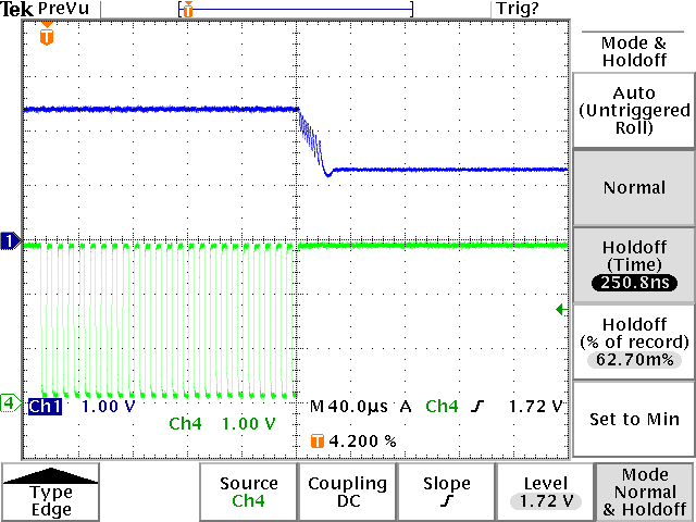
4. Frequency switching response time measurement
When the full assist mode is used and measure the frequency switching time, does the below two method has difference in the response time?
(a) Send the command (VCO parameter and frequency setting) in the same time, and trigger it by the CS signal rising edge after sending commands. (Clock frequency 40MHz is assumed)
(b) VCO three parameters and frequency are manually set, and then the trigger it by the CS signal rising edge after sending frequency setting.
Currently, it is measured with (b) method using TICS Pro.
However, the measurement is much different from the measurement (~60us difference).
So they want to identify the cause.
Please see below for the measurement setup.
- Power supply: +3.3V coming from the external DC power supply.
- Loop filter uses R and C with the constants canclulated with PLLatinum Sim
- The EVM is controlled with PC via USB2ANY
Best regards,
Kazuki Itoh