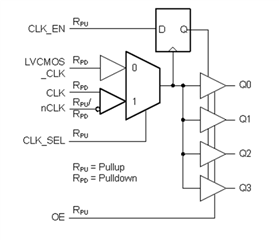
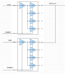
Does the 1G output enable disable the output buffer to allow 2 different LMK1C1102 devices to drive the same signal - as in the pic below? Is it a Hi-Z output when disabled or driven low? I'm trying to select between 2 different clocks.
Does the 1G output enable disable the output buffer to allow 2 different LMK1C1102 devices to drive the same signal - as in the pic below? Is it a Hi-Z output when disabled or driven low? I'm trying to select between 2 different clocks.