This thread has been locked.

If you have a related question, please click the "Ask a related question" button in the top right corner. The newly created question will be automatically linked to this question.

CDCE913: How to obtain clock output syncronization ( stable phase relationship )

Part Number: CDCE913
Other Parts Discussed in Thread: CDCE6214

Dear TI support team,

I'm evaluating part CDCE913 to obtain two clock, one 20MHz and one 80MHz. Crystal is 16MHz, PLL freq is 160MHz, output frequency values are OK, used Y2 and Y3 output.

In the application the phase relationship of the two clock needs to be know, or set to a predefined value.

At the moment I'm not able to get this, phase looks random and not controllable, sometime is good, sometimes is not.

What I've tried to do:

  1. configure all register to get required frequency
  2. set Pdiv2 and Pdiv3 to zero ( reset and stand by )
  3. stop PLL ( PWDN = 1 )
  4. set Pdiv2 and Pdiv3 to 2 and 8 to get the correct frequency
  5. start PLL ( PWDN = 0 )

what I found is that when PLL restarts the two output restart from random values, and not always 0 as they should do ( at this point I'm assuming the have to start from value 0), like there is some sort of glitch happening.

after PLL lock time the two signal reach the desired frequency, but being the start condition undeterminable, then the phase is also not determinable.

I have some oscilloscope capture to show:

expected behaviour, the two output restarts from 0

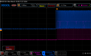
erroneous behaviour ( different glitches )

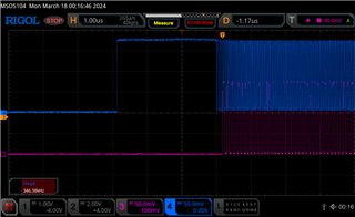
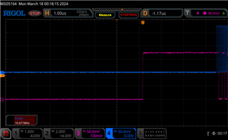
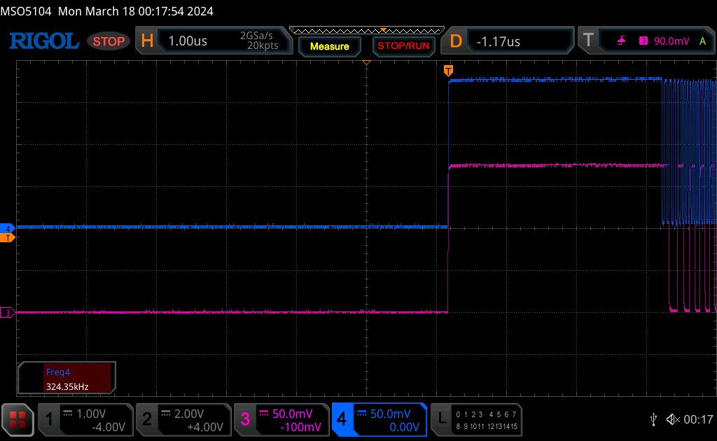
could you please advise on how to get a stable start up condition?

Best regards,

Antonio

  • Hello,

    The CDCE913 does not have an output synchronization feature. I recommend using the CDCE6214 as that part can achieve the results you are looking for.

    Best,

    Cris

  • Hi Cris,

    thank you for suggesting a different part that can handle the phase requirement, unfortunately after a brief look it seems that CDCE6214 requires significative more power. In the application power is constrained and CDCE913 is already at limit.

    Is there any other option or part that can fit with lower power requirement?

    Remaining on CDCE913, if i write the config in EEPROM and start up the device and never reconfigure the device, do you think it will always start in the same condition? It is not necessary in the application to change frequency at run time.

    Best regards,

    Antonio

  • Antonio,

    There is not phase synchronization available in the CDCE913 whatsoever. We cannot guarantee that the output clocks will be synchronized at startup, only that the output-to-output skew is within 50ps. For actual synchronization, the CDCE6214 would be required. For the required frequencies, unused outputs and prescaler b can be powered down for reduced power consumption.
    Thanks,

    Kadeem

  • Hi Kadeem,

    thank you for confirming start up behaviour of CDCE913.

    So, if CDCE6214 is the only viable solution, would be possible to have an estimation of the current consumption of the part in this specific use case? Crystal oscillator input with two LVCMOS output of 20MHz and 80 MHz.

    Best regards,

    Antonio

  • Antonio,
    We can have this for you by tomorrow.
    Thanks,

    Kadeem

  • Antonio,

    The current consumption in this configuration with 3.3V is 48mA (room temperature, 1 device) with the outputs unterminated, and 64mA with the outputs terminated.
    For 1.8V, the current consumption is 29mA for unterminated and 52mA terminated.
    Thanks,
    Kadeem

  • Hi Kadeem,

    thank you for the promptly support on this measure.

    Unfortunately, the current values are quite above the maximum available for this function, I have to reevaluate some parts of the design and check if this can fit in.

    Best regards,

    Antonio

  • Antonio,

    Please keep me updated.

    Thanks,
    Kadeem