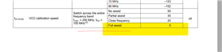
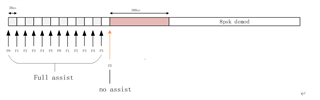
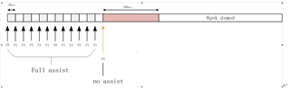
I am using LMX2594 for fast frequency switching in full assist mode, with the goal of compressing the frequency switching time to within 10us. During testing, it was found that in most cases, PLL can be locked within 10us, but there may be the following issues:
1. There is a small probability of PLL locking signal approaching 50us
2. There is a small probability that the PLL has been locked, but the frequency is still oscillating, resulting in poor signal quality and errors in the received signal
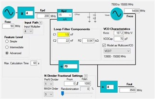
We are a frequency hopping system that uses six frequency points, 13268MHz, 13428MHz, 13588 MHz, 13748MHz, 13908 MHz, 33364MHz, for testing. Each frequency point switches once at 40us for synchronization and demodulation.
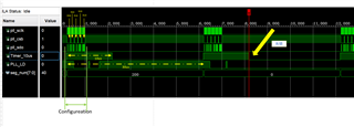
The specific usage process is as follows:

Step 1
The first step is to configure the initialization register
00201e
00201c
4E0003
4D0000
4C000C
4B0840
4A0000
49003F
480001
470081
46C350
450000
4403E8
430000
4201F4
410000
401388
3F0000
3E0322
3D00A8
3C0000
3B0001
3A9001
390020
380000
370000
360000
350000
340820
330080
320000
314180
300300
2F0300
2E07FC
2DC0DF
2C1FA3
2B0001
2A0000
290001
280000
2701F4
260000
258404
240046
230004
220000
211E21
200393
1F43EC
1E318C
1D318C
1C0488
1B0002
1A0DB0
190C2B
18071A
17007C
160001
150401
14E048
1327B7
120064
11012C
100080
0F064F
0E1E70
0D4000
0C5001
0B0018
0A12D8
090604
082000
0700B2
06C802
0500C8
040A43
030642
020500
010808
00271C
Step 2
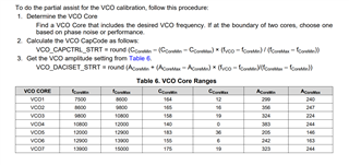
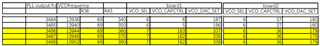
Calibrate the frequency points of the application, using VCO with frequencies ranging from 13268MHz to 14068MHz
Read the calibration values corresponding to R110, R111, and R112, and store them
Step 3
Set the three related force values of R8 and R20 to 1
Step 4
When setting the usage frequency, read the values stored in the second step and directly configure R20, R19, and R16
Please help analyze the cause of the problem;