A related question is a question created from another question. When the related question is created, it will be automatically linked to the original question.
You posted documents with confidentiality markers on them, so I deleted them from your post. In the future, please do not post documents with confidentiality markers on public forums
Edited: apologies, I got my symbols on poster names mixed up and thought this was coming from a TI internal source as opposed to an external source. Please disregard prior notice - it's your schematic, if you can post it here that's at your discretion.
That said, I have reviewed the schematic before deletion, and I see no issues.
Strictly speaking, they are not required to get functional output clocks. They may be required to get high-performance, low-noise output clocks.
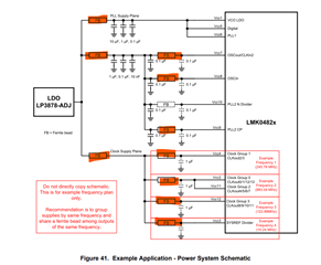
The LMK0482x has many internal LDOs to filter spurious influences in the <20MHz range, and on-chip bypass capacitance and bondwire inductance that forms low-pass filters cutting off spurious noise in the >200MHz range. Broadly speaking, these numbers can vary a bit, but the key takeaway is that there is an interval of about a decade from low 10s of MHz to low 100s of MHz where there are no mechanisms on-chip to filter out spurious influence.
At a minimum, we recommend placing ferrite beads between clock output power supplies that have different operating frequencies, since clock frequencies are commonly in the unfiltered range or have harmonics in that range. A second ferrite on top of all the clock supplies is generally not needed.
If OSCin and OSCout are the same frequency, or if OSCout is unused, those supplies can share a ferrite bead. If OSCin is the same frequency as one of the clock output groups, this also allows OSCin (and possibly OSCout) to share a ferrite bead with one or more of the CLKout supplies. The one case where this isn't recommended is for extremely tight (<1ps) POR-to-POR variation in OSCin to CLKout phase skew, and even this can be mitigated with ZDM and careful SYNC setup.
The N-divider supply doesn't usually need a ferrite bead since the noise is high frequency and is all contained on-chip.
We strongly recommend a ferrite on PLL2 charge pump (CP) supply. There's no LDO on this supply, and it can inject spurs directly onto the control voltage of the VCO, which will show up on all outputs. The PLL loop bandwidth helps to reject some of these spurs at higher frequencies, but for sub-100MHz spurs a ferrite bead can help a lot.
Again, a separate secondary ferrite bead for the PLL2 supplies is probably unnecessary.
The other supplies are combined for several reasons:
The LDO on the VCO is designed for large PSRR in-band.
We know the noise profile of the digital supply, and it's either rejected by the LDO or contained on-chip.
PLL1 supplies operate on a PLL with such low loop bandwidth that any noise from the digital supplies will not impact the overall phase noise performance. The VCO supply does not really emit noise - the primary spur is in the GHz range, and this is contained on-chip.
The only possible noise contamination is from CLKinX to VCO, if one is not a strict multiple of the other. It may be worthwhile to separate the PLL1 supply from the other two with a ferrite bead, if the input frequency is in the 10-100MHz range.
In the end, the decision of how many ferrite beads to use comes down to your application's tolerance for spurious noise. If you need the best performance you can get, place the ferrites to isolate dissimilar 10-200MHz signals from each other. You can relax the ferrite requirements if your application is tolerant to spurs, or has lax jitter requirements (e.g. digital clocks that just need distinct monotonic signals). I generally advise people to at least place some footprints for ferrite beads, and if you don't need them you can put 0Ω resistors in instead - the overall cost difference is pretty negligible if it turns out you don't need these components, and is much cheaper than a re-spin of the PCB if it turns out you do need them.